10-3
10-2 Preparing for Operation
OMNUC G5-series AC Servomotors and Servo Drives User’s Manual (with Built-in EtherCAT Communications)
10
Operation
Checking the EtherCAT Communications Connectors
The EtherCAT Communications Cables must be connected securely to the EtherCAT
Communications Connectors (ECAT IN and ECAT OUT).
Checking the Node Address Setting
Make sure that the node address is correctly set on the node address rotary switches.
Precautions for Correct Use
Do not change the setting on the rotary switches after the power supply has been turned ON.
The node address rotary switches can be set to between 00 and 99.
The node address used over the network is determined by the value set on the rotary switches.
If the node address is not between 00 and 99, a Node Address Setting Error (Error 88.0) will occur.
Turning ON the Power Supply
Turn ON the control circuit power after you conduct the pre-power-ON checking.
You may turn ON the main circuit power, but it is not a required.
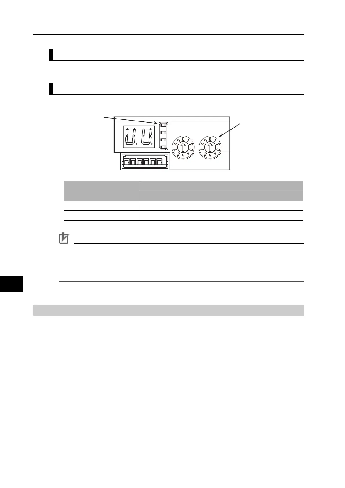
CN5
ADR
x10
x1
Status indicators
@ RUN
@ ERR
@ L/A IN
@ L/A OUT
Rotary switches for
node address setting
Rotary switch setting
Contents
Connection to CJ1W-NC281/NC481/NC881/NCF81/NC482/NC882
00 The Position Control Unit sets the node address.
01 to 99 The rotary switch setting is used as the node address.

 Loading...


