9-11
9-2 Gain Settings
OMNUC G5-series AC Servomotors and Servo Drives User’s Manual (with Built-in EtherCAT Communications)
9
Details on Servo Parameter Objects
Select the conditions for switching between gain 1 and gain 2 when the Gain Switching Input
Operating Mode Selection (3114 hex) is set to 1.
Explanation of Settings
*1. The Gain Switching Delay Time in Position Control (3116 hex) becomes effective when the gain is
switched from 2 to 1.
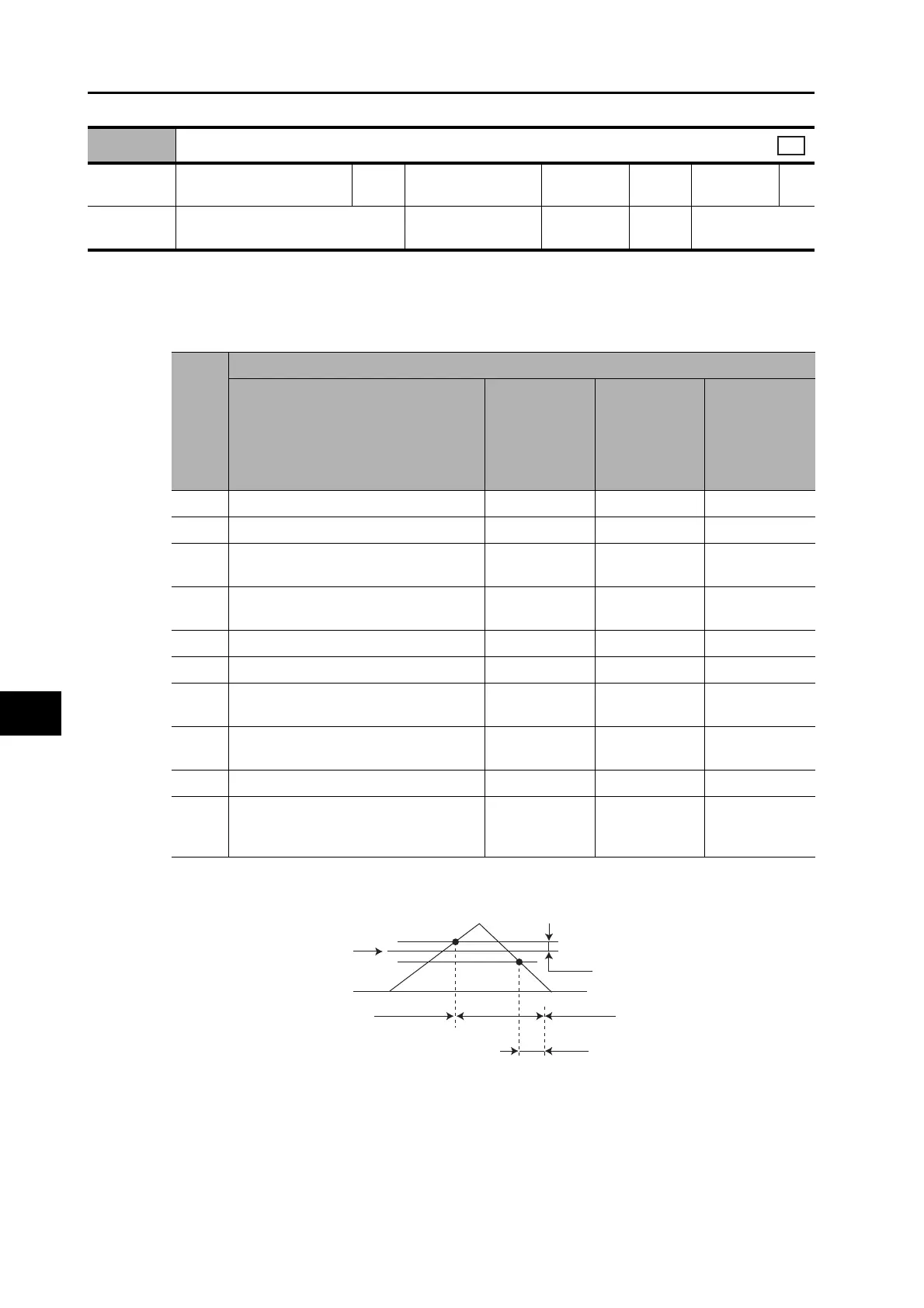
*2. The Gain Switching Hysteresis in Position Control (3118 hex) is defined in the drawing below.
If object 3117 hex is less than object 3118 hex, object 3117 hex will automatically be set to the same
value as object 3118 hex.
*3. When the Gain Switching command of EtherCAT communications is 0, the gain switches to gain 1.
When the command is 1, the gain switches to gain 2.
*4. Set the percentage of the rated torque.
Example: To set 10% of the rated torque, set the set value would be 10.
*5. The position error is set according to the encoder resolution (i.e., pulses) for position control and
according to the external encoder resolution (i.e., pulses) for fully-closed control.
3115 hex
Switching Mode in Position Control
Setting
range
0 to 10 Unit −
Default
setting
0
Data
attribute
B
Size 2 bytes (INT16) Access RW
PDO
map
Not possible.
csp
3115
hex
set
value
Description
Gain switching conditions
Gain
Switching
Delay Time in
Position
Control
(3116 hex)
*1
Gain
Switching
Level in
Position
Control
(3117 hex)
Gain
Switching
Hysteresis in
Position
Control
(3118 hex)
*2
0 Always Gain 1 (3100 to 3104 hex). Disabled Disabled Disabled
1 Always Gain 2 (3105 to 3109 hex). Disabled Disabled Disabled
2
Gain switching command input via
EtherCAT communications
*3
Disabled Disabled Disabled
3
Command torque value (Refer to Figure
A.)
Enabled
Enabled
*4
(%)
Enabled
*4
(%)
4 Always Gain 1 (3100 to 3104 hex). Disabled Disabled Disabled
5 Command speed (Refer to Figure B) Enabled Enabled (r/min) Enabled (r/min)
6
Pulse position error (Refer to Figure C.)
Enabled
Enabled
*5
(pulse)
Enabled
*5
(pulse)
7
Whether there is a position command
(Refer to Figure D.)
Enabled Disabled Disabled
9 Actual motor speed (Refer to Figure B). Enabled Enabled (r/min) Enabled (r/min)
10
Combination of whether there is a
position command and actual motor
speed (Refer to Figure E.)
Enabled
Enabled
*6
(r/min)
Enabled
*6
(r/min)
3117 hex
0
3118 hex
3116 hex
Gain 1
Gain 2
Gain 1

 Loading...


