2-49
2-4 External and Mounting Dimensions
OMNUC G5-series AC Servomotors and Servo Drives User’s Manual (with Built-in EtherCAT Communications)
2
Models and External Dimensions
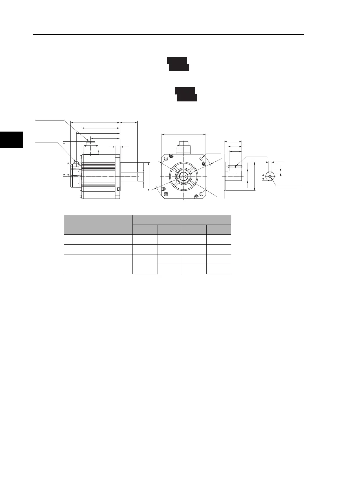
2 kW/3 kW (without Brake)
R88M-K2K010F (-S2)/-K3K010F (-S2)
R88M-K2K010C (-S2)/-K3K010C (-S2)
2 kW/3 kW (with Brake)
R88M-K2K010F-B (S2)/-K3K010F-B (S2)
R88M-K2K010C-B (S2)/-K3K010C-B (S2)
Note. The standard models have a straight shaft. Models with a key and tap are indicated with S2 at the
end of the model number.
INC
ABS
INC
ABS
Encoder
connector
Motor and brake
connector
176×176
80
55
50
M3, through
(Shaft end specifications with key and tap)
φ35h6
4−φ13.5
φ200
φ233
φ114.3h7
M12 (depth 25)
10h9
8
30
LM
KB2
KB1
80LL
140
60
3.218
φ
35h6
φ114.3h7
Model
Dimensions (mm)
LL LM KB1 KB2
R88M-K2K010@ 163.5 119.5 82.5 141.5
R88M-K3K010@ 209.5 165.5 128.5 187.5
R88M-K2K010@-B@ 192.5 148.5 82.5 170.5
R88M-K3K010@-B@ 238.5 194.5 128.5 216.5

 Loading...


