2-6SectionOffset and Gain Adjustment
28
Note Input adjustments can be performed more accurately in conjunction with mean
value processing.
2-6-2 Offset and Gain Adjustment Procedures
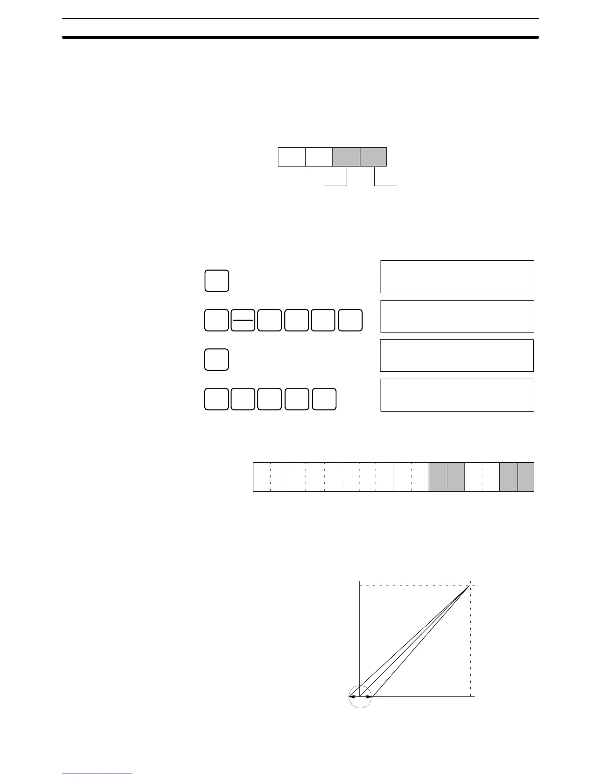
To specify the input number to be adjusted, write the value to the rightmost byte
of IR word n as shown in the following diagram.
(Rightmost)
(Leftmost)
Word n
Input to be adjusted (1 to 8)
I/O specification
2: Input (fixed)
For the IR word addresses, n = 100 + 10 x unit number.
For Units #A to #F (10 to 15), n = 400 + 10 x (unit number – 10).
The following example uses input number 1 adjustment for illustration. (The unit
number is 0.)
CLR
00000
SHIFT
CH
*
1
B
0
A
0
A
MONTR
c100
0000
CHG
PRES VAL?
c100 0000 ????
0
A
0
A
2
C
1
B
WRITE
c100
0021
The IR word n+1 bits shown in the following diagram are used for adjusting offset
and gain.
15 14 13 12 11 10 09 08 07 06 05 04 03 02 01 00
Bit
Word n+1
Clear bit
Set bit
Gain bit
Offset bit
The procedure for adjusting the analog input offset is explained below. As shown
in the following diagram, the offset is adjusted by sampling inputs so that the
conversion value becomes 0.
10 V0
0FA0
Offset adjustment input range
Input signal range:
–10 to 10 V
Specifying Input Number
to be Adjusted
Bits Used for Adjusting
Offset and Gain
Offset Adjustment

 Loading...


