!
!
4-2SectionNomenclature and Functions
71
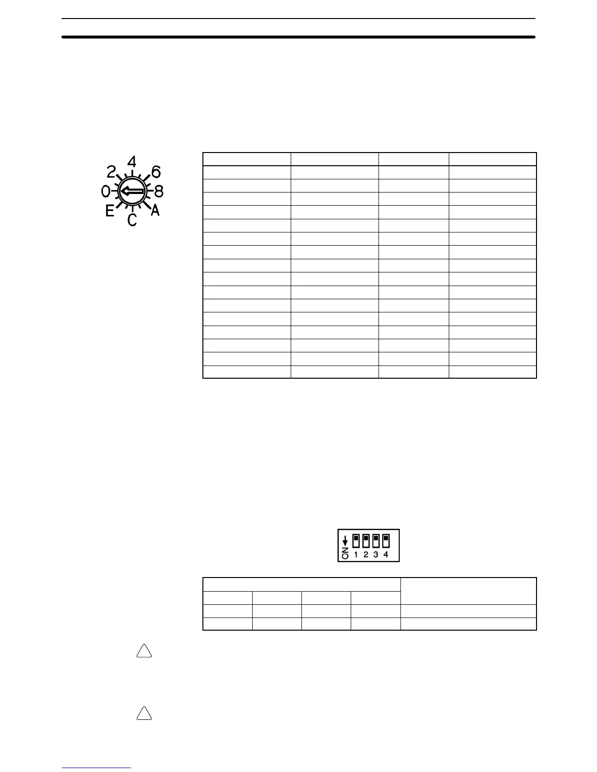
4-2-2 Unit Number Switch
The CPU Unit and Analog I/O Unit exchange data via the IR area and the DM
area. The IR and DM word addresses that each Analog Input Unit occupies are
set by the unit number switch on the front panel of the Unit.
Always turn off the power before setting the unit number. Use a flat-blade screw-
driver, being careful not to damage the slot in the screw. Be sure not to leave the
switch midway between settings.
Switch setting Unit number IR words DM words
0 Unit #0 IR 100 to 109 DM 1000 to 1099
1 Unit #1 IR 110 to 119 DM 1100 to 1199
2 Unit #2 IR 120 to 129 DM 1200 to 1299
3 Unit #3 IR 130 to 139 DM 1300 to 1399
4 Unit #4 IR 140 to 149 DM 1400 to 1499
5 Unit #5 IR 150 to 159 DM 1500 to 1599
6 Unit #6 IR 160 to 169 DM 1600 to 1699
7 Unit #7 IR 170 to 179 DM 1700 to 1799
8 Unit #8 IR 180 to 189 DM 1800 to 1899
9 Unit #9 IR 190 to 199 DM 1900 to 1999
A Unit #A IR 400 to 409 DM 2000 to 2099
B Unit #B IR 410 to 419 DM 2100 to 2199
C Unit #C IR 420 to 429 DM 2200 to 2299
D Unit #D IR 430 to 439 DM 2300 to 2399
E Unit #E IR 440 to 449 DM 2400 to 2499
F Unit #F IR 450 to 459 DM 2500 to 2599
Note 1. Switches A to F can be set for the C200HX/HG-CPU5j-E/6j-E. Setting
numbers A to F for C200H, C200HS, C200HE, or C200HX/HG-
CPU3j-E/4j-E PCs will cause an I/O UNIT OVER error and the Unit will
not operate.
2. If two or more Special I/O Units are assigned the same unit number, an I/O
UNIT OVER error will be generated and the PC will not operate.
4-2-3 Operation Mode Switch
The operation mode switch on the back of the Unit is used to set the operation
mode to either normal mode or adjustment mode (for adjusting offset and gain).
Pin number
Mode
1 2 3 4
OFF OFF OFF OFF Normal mode
ON OFF OFF OFF Adjustment mode
Caution Do not set the pins to any combination other than those shown in the above
table.
Be sure to set pins 2, 3, and 4 to OFF.
Caution Be sure to turn off the power to the PC before mounting or removing any Units.

 Loading...


