EasyManua.ls Logo

Omron SYSMAC C200H-AD003 User Manual

Omron SYSMAC C200H-AD003
145 pages
To Next Page IconTo Next Page
To Previous Page IconTo Previous Page
Page #50 background image
3-1SectionSpecifications
38
3-1 Specifications
3-1-1 General Specifications
All general specifications of the C200H-DA003/DA004 Analog Output Units
conform to those of the C200H, C200HS, and C200HX/HG/HE Series.
3-1-2 Performance Specifications
Item C200H-DA003 C200H-DA004
Number of analog outputs 8
Output signal range (note 1) 0 to 10 V
–10 to 10 V
1 to 5 V
4 to 20 mA
Output impedance 0.5 max. ---
Max. output current 12 mA ---
Max. load resistance --- 600 max.
Resolution 1/4000 (full scale)
Set data 16-bit binary data
Accuracy
(note 2)
23°±2°C
±0.3% of full scale ±0.5% of full scale
(note 2)
0° to 55°C
±0.5% of full scale ±0.8% of full scale
Conversion time (note 3) 1.0 ms/point
Isolation Between input terminals and PC: photocoupler
(No isolation between individual output signals.)
External connectors 28-point terminal block (M3 screws)
Power consumption
100 mA max. at 5 VDC
p
200 mA max. at 26 VDC 250 mA max. at 26 VDC
Dimensions 34.5 x 130 x 128 (W x H x D) mm (refer to Appendix
A Dimensions)
Weight 450 g max.
Note 1. The output signal range can be set individually for each output.
2. The accuracy is given for full scale. For example, an accuracy of ±0.3%
means a maximum error of ±12 (BCD).
3. This is the time required for converting and outputting the PC data. It takes at
least one cycle for the data stored in the PC to be read by the Analog Output
Unit.
By executing an I/O refresh, the conversion time may be extended by an
additional 0.3 ms approximately.
4. The default setting for the load resistance of the C200H-DA004 is 250 .
When using a load resistance other than 250 , perform the offset and gain
adjustment as required.

Table of Contents

Question and Answer IconNeed help?

Do you have a question about the Omron SYSMAC C200H-AD003 and is the answer not in the manual?
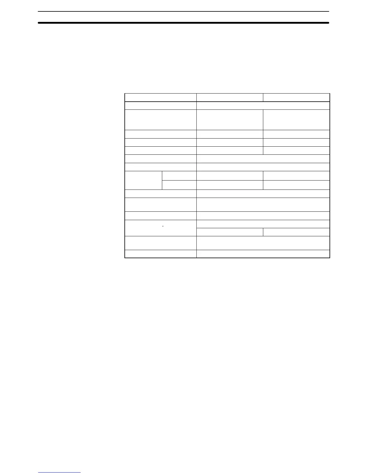
Omron SYSMAC C200H-AD003 Specifications

General IconGeneral
BrandOmron
ModelSYSMAC C200H-AD003
CategoryI/O Systems
LanguageEnglish

Summary

Precautions and Safety Information

Intended Audience

Defines the target audience for the manual.

General Precautions

Provides general guidelines for safe and proper product use.

Safety Precautions

Highlights critical safety warnings and measures to prevent injury.

Operating Environment Precautions

Specifies conditions to avoid for reliable system operation.

Application Precautions

Outlines precautions for specific product applications and usage.

System Design and Configuration

Features and Functions

Describes the capabilities and operational features of the analog I/O units.

Basic Configuration

Illustrates the basic setup and components of the system.

Setting the Unit Number

Explains how to assign a unique number to each unit in the system.

Operating Procedure

Details the steps for initial installation and setup of the units.

C200H-AD003 Analog Input Unit

Specifications

Lists the technical specifications and performance parameters of the unit.

Nomenclature and Functions

Identifies unit components and their respective functions.

Wiring

Provides instructions and diagrams for connecting the unit.

IR and DM Areas

Details the allocation and use of internal memory areas for data.

Using the Functions

Explains how to utilize various functions like signal range and processing.

Error Processing

Covers error detection, troubleshooting, and countermeasures.

Offset and Gain Adjustment

Describes the calibration process for input signals.

C200H-DA003/DA004 Analog Output Units

Specifications

Lists technical specifications and performance parameters for output units.

Nomenclature and Functions

Identifies unit components and their respective functions.

Wiring

Provides instructions and diagrams for connecting the output units.

IR and DM Areas

Details memory area allocation and usage for output units.

Using the Functions

Explains how to set outputs, signal ranges, and hold functions.

Offset and Gain Adjustment

Describes the calibration process for output signals.

Error Processing

Covers error detection, troubleshooting, and countermeasures for output units.

C200H-MAD01 Analog I/O Unit

Specifications

Lists technical specifications and performance parameters for the combined I/O unit.

Nomenclature and Functions

Identifies unit components and their respective functions.

Wiring

Provides instructions and diagrams for connecting the Analog I/O unit.

IR and DM Areas

Details memory area allocation and usage for the Analog I/O unit.

Analog Input Functions

Explains functions related to analog signal input processing.

Analog Output Functions

Explains functions related to analog signal output processing.

Ratio Conversion Function

Describes the function for converting analog inputs to analog outputs.

Offset and Gain Adjustment

Describes the calibration process for analog I/O signals.

Error Processing

Covers error detection, troubleshooting, and countermeasures for the unit.

Sample Programs

Sample Program 1: Obtaining Analog Input Unit Conversion Values

Program to obtain analog input conversion values.

Sample Program 2: Writing Analog Output Unit Set Values

Program to write analog output unit set values.

Sample Program 3: Upper- and Lower-limit Alarm (Regular Monitoring)

Program for upper/lower limit alarm checks on A/D or D/A values.

Sample Program 4: Upper- and Lower-limit Alarm (With Sequence)

Program for sequential upper/lower limit alarm checks.

Sample Program 5: Scaling

Program to convert A/D values to BCD data with scaling.

Sample Program 6: Binary-to-BCD Conversion

Program to convert 16-bit binary data to signed BCD.

Sample Program 7: Square Root Calculation

Program to convert quadratic curve data to linear data.

Sample Program 8: Mean Value Processing

Program to calculate mean value from sampled data.

Sample Program 9: Peak Value Holding

Program for analog output peak value holding.

External Dimensions

Changes From Earlier Models

Differences Between C200H-AD003 and C200H-AD001/AD002

Compares features and functions with previous analog input models.

Differences Between C200H-DA003/004 and C200H-DA001/002

Compares features and functions with previous analog output models.

Related product manuals