4-2SectionNomenclature and Functions
70
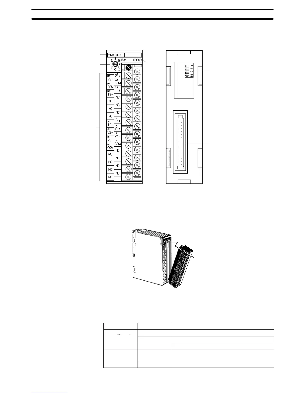
4-2 Nomenclature and Functions
Model label
Unit number setting switch
Terminal block mounting
screw (black M3)
External input terminal
block (M3)
Indicators
Operation mode switch
Backplane connector
Front Back
The terminal block is attached by a connector. It can be removed by loosening
the black mounting screw. When removing the terminal block after wiring, re-
move the wire connected to the top terminal of the right column.
Check to be sure that the black terminal block mounting screw is securely tight-
ened to a torque of 0.5 N S m.
Fasten the mounting screw.
4-2-1 Indicators
The RUN and ERROR indicators show the operating status of the Unit. The fol-
lowing table shows the meanings of the indicators.
LED Indicator Operating status
RUN (green)
Lit Operating in normal mode.
Flashes Operating in adjustment mode.
Not lit Abnormal (Unit operation stopped)
ERROR (red)
Lit Error occurred. The error codes are stored in bits
08 to 15 of word n+9.
Not lit Other than the above.

 Loading...


