4-6SectionAnalog Output Functions
87
4-6-2 Output Hold Function
The Analog I/O Unit stops conversion under the following circumstances, and
output the value set by the output hold function.
1, 2, 3... 1. When the Conversion Enable Bit is OFF. (Refer to 4-4-1 IR Area Allocation
and Contents and 4-6-4 Starting and Stopping Conversion.)
2. In adjustment mode, when something other than the output number is out-
put during adjustment. (Refer to 4-8-3 Output Offset and Gain Adjustment
Procedures.)
3. When there is an output setting error. (Refer to 4-6-5 Output Setting Errors
and 4-9-1 Troubleshooting Procedures.)
4. When a fatal error occurs at the PC. (Refer to the C200HX/HG/HE Program-
ming Manual.)
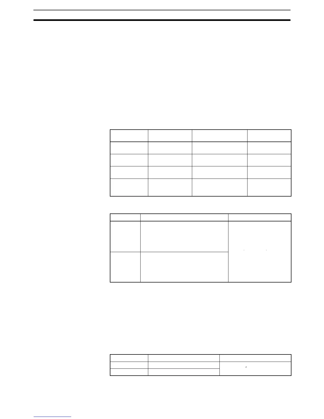
CLR, HOLD, or MAX can be selected for the output status when conversion is
stopped.
Output signal
range
CLR HOLD MAX
0 to 10 V –0.5 V (Min.–5%
of full scale)
Voltage that was output
just prior to stop.
10.5 V (Max.+5%
of full scale)
–10 to 10 V 0.0 V Voltage that was output
just prior to stop.
11.0 V (Max.+5%
of full scale)
1 to 5 V 0.8 V (Min.–5% of
full scale)
Voltage that was output
just prior to stop.
5.2 V (Max.+5% of
full scale)
4 to 20 mA 3.2 mA (Min.–5%
of full scale)
Current that was output
just prior to stop.
20.8 mA
(Max.+5% of full
scale)
In order to specify the the output hold function, use a Peripheral Device to set the
DM words shown in the following table.
DM word Function Set value
DM (m+2) Output 1: Output status when stopped
xx00: CLR
0 output
xx01: HOLD
Hold output value
prior to stop
DM (m+3) Output 2: Output status when stopped
xx02: MAX
Output maximum
value of range
Set any value in the
leftmost bytes (xx).
For the DM word addresses, m = 1000 + 100 x unit number (Units #A to #F = Unit
numbers 10 to 15).
Note After making the DM settings from a Peripheral Device, it will be necessary to
either power up the PC again or turn ON the Special I/O Unit Restart Bit in order
to transfer the contents of the DM settings to the Special I/O Unit. For details re-
garding the Special I/O Unit Restart Bit, refer to 4-9-4 Restarting Special I/O
Units.
4-6-3 Writing Set Values
Analog output set values are written to IR words n+1 and n+2.
Word Function Stored value
n+1 Output 1 set value
16-bit binary data
n+2 Output 2 set value

 Loading...


