4-4SectionIR and DM Areas
78
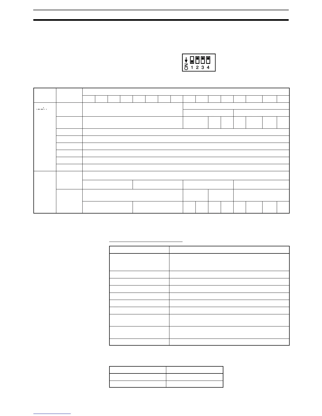
For adjustment mode, set the operation mode switch on the rear panel of the
Unit as shown in the following diagram. When the Unit is set for adjustment
mode, the RUN indicator on the front panel of the Unit will flash.
The allocation of IR words and bits is shown in the following table.
I/O Word
Bits
15 14 13 12 11 10 9 8 7 6 5 4 3 2 1 0
Output
o
CPU)
16
3
16
2
16
1
16
0
n+9
Error code Not used. Disconnection
detection
Not used.
16
1
16
0
Input
2
Input
1
Note For the IR word addresses, n = 100 + 10 x unit number.
For Units #A to #F (10 to 15), n = 400 + 10 x (unit number – 10).
Set Values and Stored Values
Item Contents
Input or output to be
adjusted
Sets input or output to be adjusted.
Leftmost digit: 1 (output) or 2 (input)
Rightmost digit: 1 or 2
Offset (Offset Bit) When ON, adjusts offset deviation.
Gain (Gain Bit) When ON, adjusts gain deviation.
Down (Down Bit) Decrements the adjustment value while ON.
Up (Up Bit) Increments the adjustment value while ON.
Set (Set Bit) Sets adjusted value and writes to EEPROM.
Clr (Clear Bit) Clears adjusted value. (Returns to default status)
Conversion value for
adjustment
The conversion value for adjustment is stored as 16
bits of binary data.
Disconnection detection 0: No disconnection
1: Disconnection
Error code Two digits, hexadecimal (00 for no error)
The disconnection detection function can be used when the input signal range is
set for 1 to 5 V (4 to 20 mA).
Input signal range Voltage/current
1 to 5 V 0.3 V max.
4 to 20 mA 1.2 mA max.
Allocation for
Adjustment Mode

 Loading...


