4-6SectionAnalog Output Functions
88
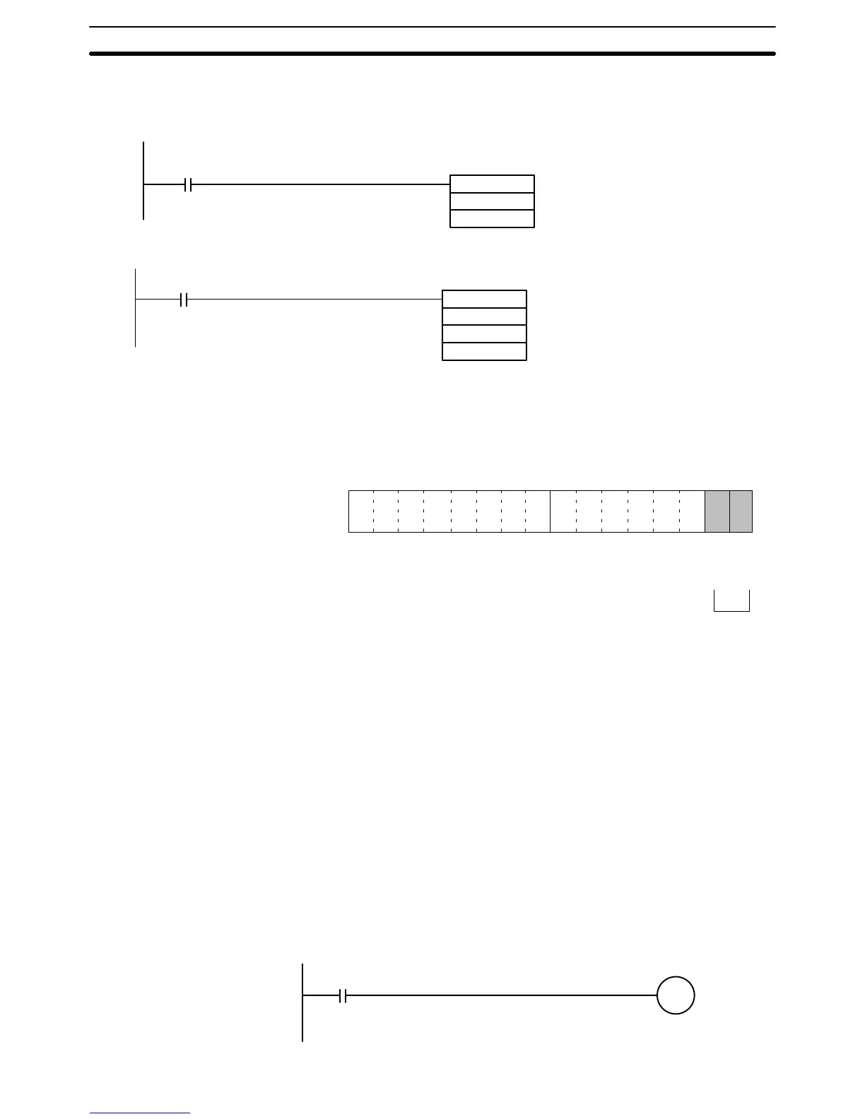
Use MOV(21) or XFER(70) to write values in the user program.
In this example, the set value from only one input is read. (The unit number is
#0.)
MOV (21)
DM0001
101
Input condition
The set value stored in DM 0001
is written to IR word 101 (output
number 1).
In this example, multiple set values are written. (The unit number is #0.)
XFER(70)
#0002
DM0001
101
Input condition
The set values stored in DM 0001
and DM 0002 are written to IR words
101 and 102 (outputs 1 and 2).
Note Turn ON the Conversion Enable Bit for converting set values into analog output.
4-6-4 Starting and Stopping Conversion
To begin analog output conversion, turn ON the corresponding Conversion En-
able Bit (word n, bits 00 and 01) from the user’s program.
15 14 13 12 11 10 09 08 07 06 05 04 03 02 01 00
Bit
Output 2
Output 1
Analog conversion is executed while
these bits are ON. When the bits are
turned OFF, the conversion is stopped
and the output data is held. (Refer to
4-6-2 Output Hold Function.)
Word n
For the IR word addresses, n = 100 + 10 x unit number.
For Units #A to #F (10 to 15), n = 400 + 10 x (unit number – 10).
The analog output when conversion is stopped will differ depending on the out-
put signal range setting. (Refer to 4-6-1 Setting Outputs and Signal Ranges.)
Conversion will not begin under the following conditions even if the Conversion
Enable Bit is turned ON.
1, 2, 3... 1. In adjustment mode, when something other than the output number is out-
put during adjustment. (Refer to 3-6-1 Adjustment Mode Operational Flow.)
2. When there is an output setting error. (Refer to 4-8-3 Output Offset and Gain
Adjustment Procedures and 4-9-2 Errors Detected by Analog I/O Unit.)
3. When a fatal error occurs at the PC. (Refer to the C200HX/HG/HE Program-
ming Manual.)
In this example, conversion is begun for analog output number 1. (The unit num-
ber is #0.)
10000
Input condition
Conversion
begins for
output
number 1.
Example 1
Example 2
 Loading...


