4-8SectionOffset and Gain Adjustment
93
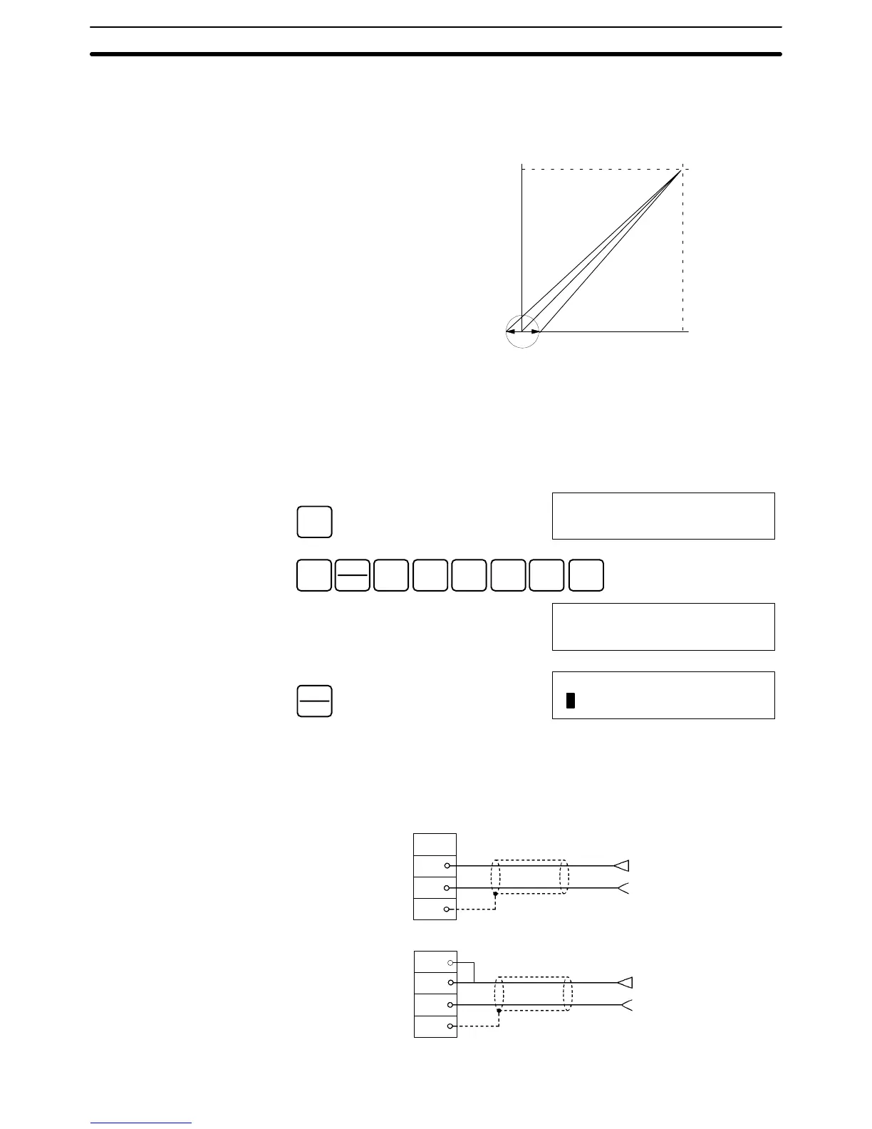
The procedure for adjusting the analog input offset is explained below. As shown
in the following diagram, the offset is adjusted by sampling inputs so that the
conversion value becomes 0.
10 V0
0FA0
Offset adjustment input range
Input signal range:
–10 to 10 V
The following example uses input number 1 adjustment for illustration. (The unit
number is 0.)
1, 2, 3... 1. Turn ON bit 00 (the Offset Bit) of IR word n+1. (Hold the ON status.)
CLR
00000
SHIFT
CONT
#
1
B
0
A
1
B
0
A
0
A
MONTR
10100
^OFF
PLAY
SET
10100
ON
The analog input’s digital conversion values while the Offset Bit is ON will be
monitored in IR word n+8.
2. Check whether the input devices are connected.
A6
A7
A8
A9
A6
A7
A8
A9
+
–
+
–
Voltage input
Input 1
Current input
Input 1
Offset Adjustment
 Loading...


