3-3SectionWiring
43
Current Output Model (C200H-DA004)
NC B0
Current output 2 (–) B1
Current output 2 (+) B2
NC B3
Current output 4 (–) B4
Current output 4 (+) B5
NC B6
Current output 6 (–) B7
Current output 6 (+) B8
NC B9
Current output 8 (–) B10
Current output 8 (+) B11
NC B12
NC B13
NCA0
Current output 1 (–)A1
Current output 1 (+)A2
NCA3
Current output 3 (–)A4
Current output 3 (+)A5
NCA6
Current output 5 (–)A7
Current output 5 (+)A8
NCA9
Current output 7 (–)A10
Current output 7 (+)A11
NCA12
NCA13
Note 1. The analog output numbers that can be used are set in the Data Memory
(DM).
2. The output signal ranges for individual outputs are set in the Data Memory
(DM). Setting is possible for every Analog Output Unit output number.
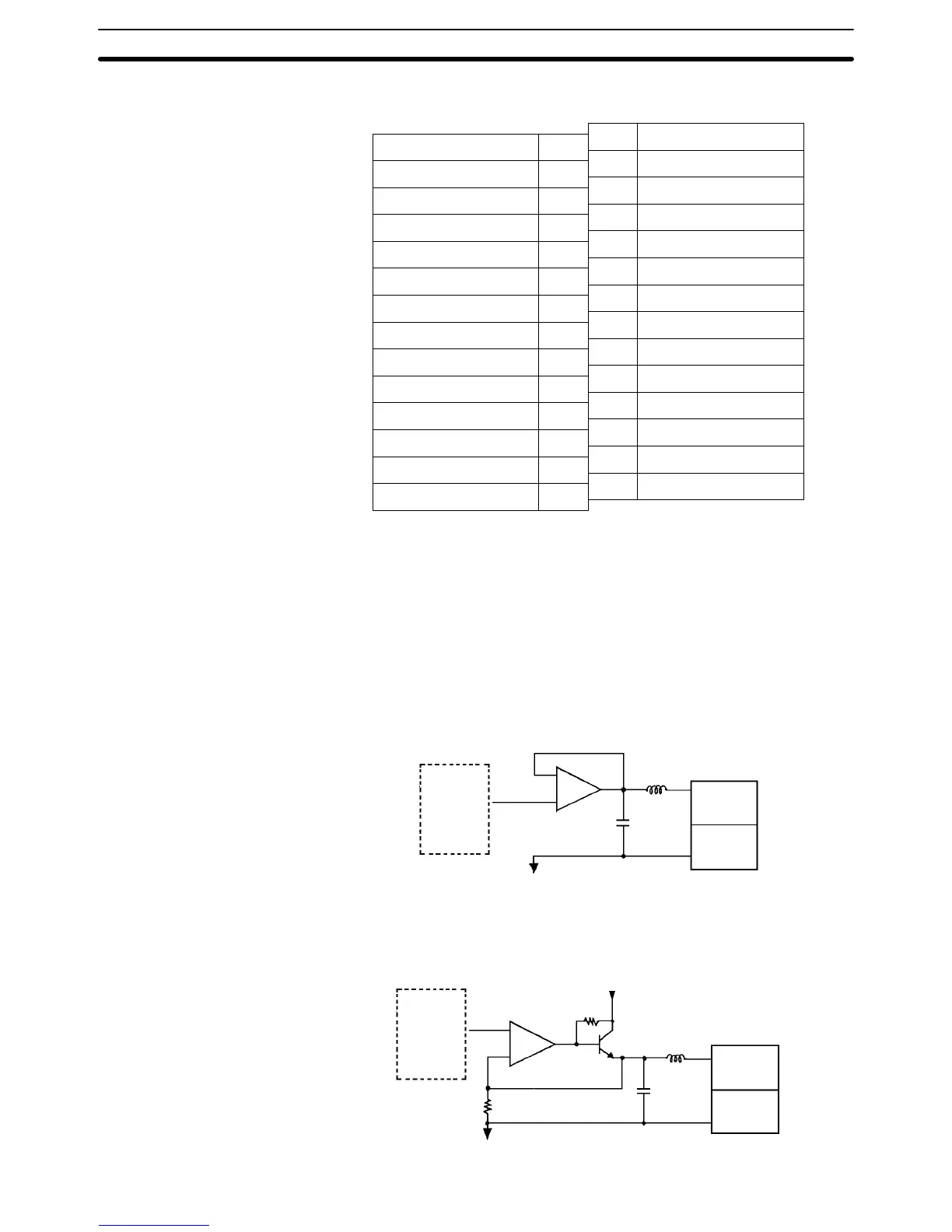
3-3-2 Internal Circuitry
The following diagrams show the internal circuitry of the analog output section.
Voltage Output Model (C200H-DA003)
Output
switch and
conversion
circuit
AMP
Voltage
output (+)
Voltage
output (–)
AG (common to all outputs)
Current Output Model (C200H-DA004)
Output
switch and
conversion
circuit
AMP
Current
output (+)
Current
output (–)
Internal power supply
 Loading...


