EasyManua.ls Logo

Omron SYSMAC C200H-DA004 User Manual

Omron SYSMAC C200H-DA004
145 pages
To Next Page IconTo Next Page
To Previous Page IconTo Previous Page
Page #37 background imageLoading...
Page #37 background image
2-5SectionUsing the Functions
25
2-5-4 Peak Value Function
The peak value function holds the maximum digital conversion value for every
input (including mean value processing). This function can be used with analog
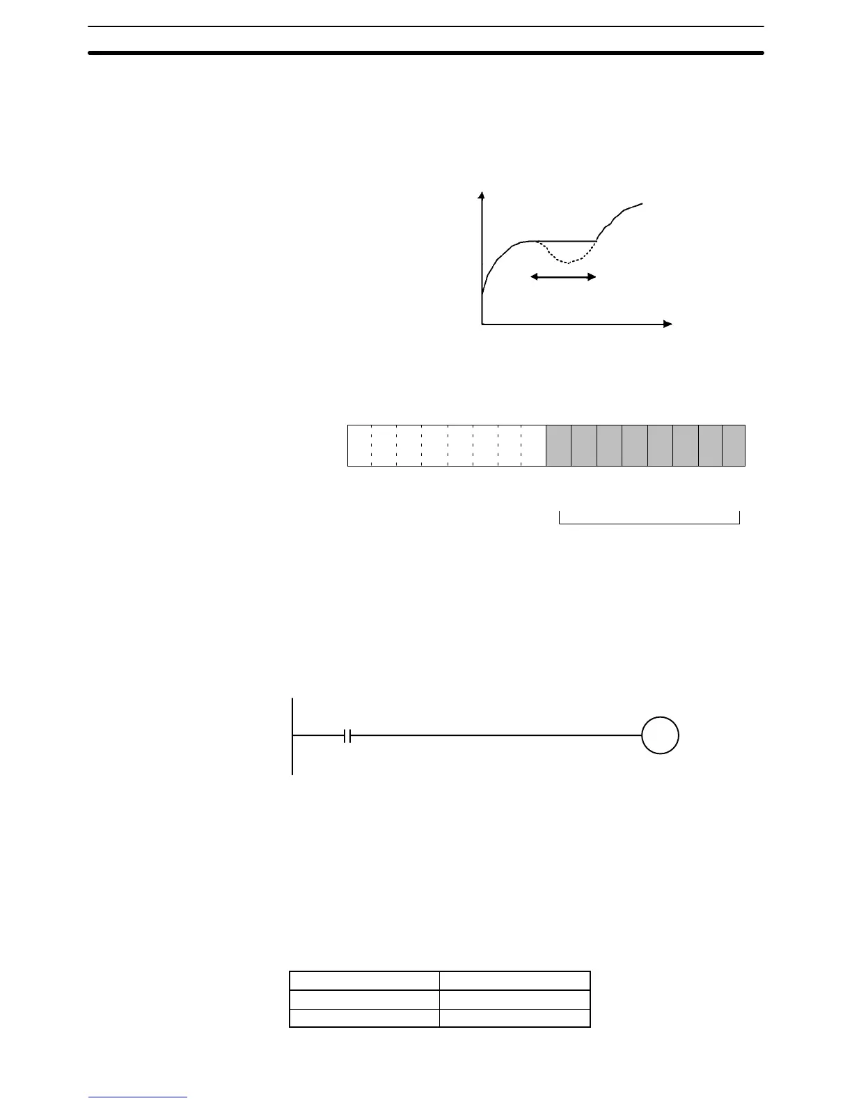
input. The following diagram shows how digital conversion values are affected
when the peak value function is used.
Peak value hold
Digital conversion value
t (Time)
The peak value function can be set individually for each input number by turning
on the respective bits (00 to 07) in IR word n.
15 14 13 12 11 10 09 08 07 06 05 04 03 02 01 00
Bit
Input 8
Input 7
Input 6
Input 5
Input 4
Input 3
Input 2
Input 1
Word n
The peak hold function will be in effect
for the above input numbers while
their respective bits are ON. The
conversion values will be reset when
the bits are turned OFF.
For the IR word addresses, n = 100 + 10 x unit number.
For Units #A to #F (10 to 15), n = 400 + 10 x (unit number – 10).
In the following example, the peak value function is in effect for input number 1,
and the unit number is 0.
10000
Input condition
The maximum
conversion
data value is
held for input
number 1.
When mean value processing is used together with the peak value function, the
mean value will be held.
As long as the peak value function is in effect, the peak value will be held even in
the event of a disconnection.
2-5-5 Input Disconnection Detection Function
When an input signal range of 1 to 5 V (4 to 20 mA) is used, input circuit discon-
nections can be detected. The detection conditions for each of the input signal
ranges are shown in the following table.
Range Current/voltage
1 to 5 V 0.3 V max.
4 to 20 mA 1.2 mA max.

Table of Contents

Question and Answer IconNeed help?

Do you have a question about the Omron SYSMAC C200H-DA004 and is the answer not in the manual?

Omron SYSMAC C200H-DA004 Specifications

General IconGeneral
BrandOmron
ModelSYSMAC C200H-DA004
CategoryI/O Systems
LanguageEnglish

Summary

OPERATION MANUAL

SYSMAC Analog I/O Units

Details on SYSMAC Analog I/O Units.

About this Manual

PRECAUTIONS

Safety Precautions

Critical safety warnings and measures for handling the equipment.

Application Precautions

Precautions for using the PC system and Analog I/O Units.

SECTION 1 System Design

Analog Input Functions

SECTION 2 C200H-AD003 Analog Input Unit

Input Specifications

Nomenclature and Functions

Wiring

IR and DM Areas

Using the Functions

Mean Value Processing

Offset and Gain Adjustment

Offset and Gain Adjustment Procedures

How to specify the output number for adjustment.

Error Processing

Troubleshooting Procedure

Procedure for troubleshooting Analog I/O Unit errors.

Errors Detected by Analog Input Unit

Details of errors detected by the Analog Input Unit and countermeasures.

Errors Detected by Analog Output Unit

Details of errors detected by the Analog Output Unit and countermeasures.

Errors Detected by Analog I/O Unit

Details of errors detected by the Analog I/O Unit and countermeasures.

SECTION 3 C200H-DA003 and C200H-DA004 Analog Output Units

Wiring

Instructions and examples for wiring Analog Output Units.

Output Specifications

SECTION 4 C200H-MAD01 Analog I/O Unit

Specifications

Specifications for the C200H-MAD01 Analog I/O Unit.

Nomenclature and Functions

Identifies unit parts and explains their functions.

Specifications

Analog Input Functions

Peak Value Function

Analog Output Functions

Output Setting Errors

Related product manuals