3-5SectionUsing the Functions
51
For the DM word addresses, m = 1000 + 100 x unit number (Units #A to #F = Unit
numbers 10 to 15).
This setting is not valid for the C200H-DA004 (current output model). The output
signal range for the C200-DA004 is 4 to 20 mA, regardless of the settings.
Note After making the DM settings from a Peripheral Device, it will be necessary to
either power up the PC again or turn ON the Special I/O Unit Restart Bit in order
to transfer the contents of the DM settings to the Special I/O Unit. For details re-
garding the Special I/O Unit Restart Bit, refer to 3-7-4 Restarting Special I/O
Units.
3-5-2 Output Hold Function
The Analog Output Units stop conversion under the following circumstances,
and output the value set by the output hold function.
1, 2, 3... 1. When the Conversion Enable Bit is OFF. (Refer to 3-4-1 IR Area Allocation.)
2. In adjustment mode, when something other than the output number is out-
put during adjustment. (Refer to 3-6-1 Adjustment Mode Operational Flow.)
3. When there is an output setting error. (Refer to 3-5-5 Output Setting Errors.)
4. When a fatal error occurs at the PC. (Refer to the C200HX/HG/HE Program-
ming Manual.)
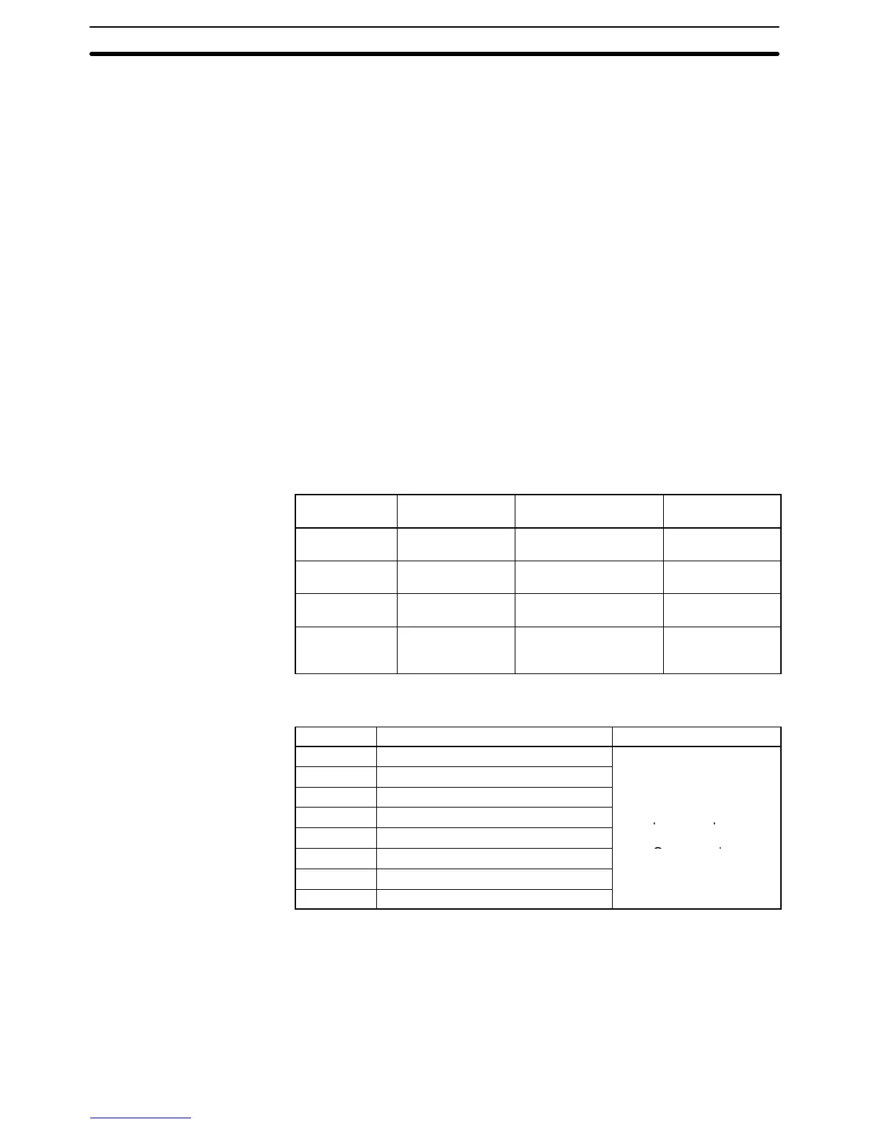
CLR, HOLD, or MAX can be selected for the output status when conversion is
stopped.
Output signal
range
CLR HOLD MAX
0 to 10 V –0.5 V (Min.–5%
of full scale)
Voltage that was output
just prior to stop.
10.5 V (Max.+5%
of full scale)
–10 to 10 V 0.0 V Voltage that was output
just prior to stop.
11.0 V (Max.+5%
of full scale)
1 to 5 V 0.8 V (Min.–5% of
full scale)
Voltage that was output
just prior to stop.
5.2 V (Max.+5% of
full scale)
4 to 20 mA 3.2 mA (Min.–5%
of full scale)
Current that was output
just prior to stop.
20.8 mA
(Max.+5% of full
scale)
In order to specify the the output hold function, set from a Peripheral Device the
DM words shown in the following table.
DM word Function Set value
DM (m+2) Output 1: Output status when stopped
xx00: CLR
e
leftmost bytes (xx).
For the DM word addresses, m = 1000 + 100 x unit number (Units #A to #F = Unit
numbers 10 to 15).
Note After making the DM settings from a Peripheral Device, it will be necessary to
either power up the PC again or turn ON the Special I/O Unit Restart Bit in order
to transfer the contents of the DM settings to the Special I/O Unit. For details re-
garding the Special I/O Unit Restart Bit, refer to 3-7-4 Restarting Special I/O
Units.
 Loading...


