2-3SectionWiring
15
2. The input signal ranges for individual inputs are set in the Data Memory
(DM). They can be set in units of analog input numbers.
3. The COM terminal is connected to the 0-V analog circuit in the Unit. Con-
necting shielded input lines can improve noise resistance.
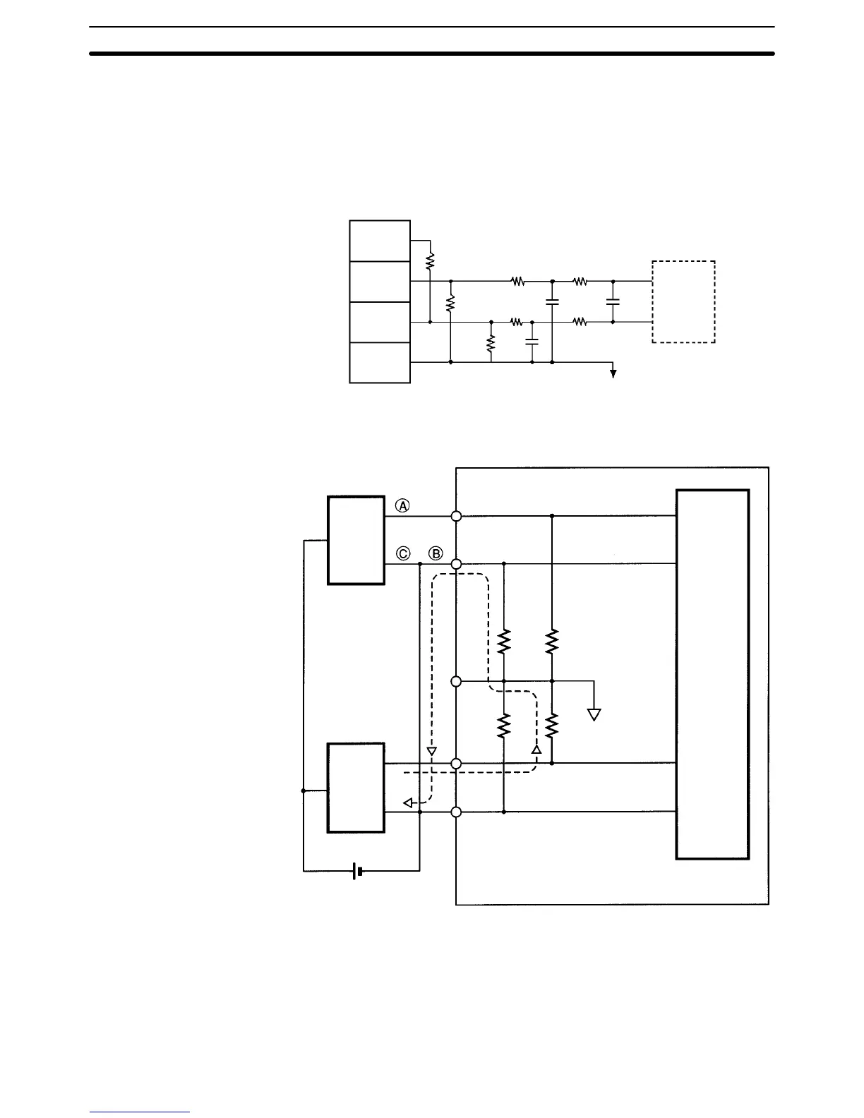
2-3-2 Internal Circuitry
The following diagram shows the internal circuitry of the analog input section.
250 Ω
1 MΩ
10 kΩ 10 kΩ
10 kΩ 10 kΩ
AG (common to all outputs)
Current
input (+)
Voltage
input (+)
Voltage
input (–)
COM
(analog
0 V)
Input circuit
and
conversion
circuit
1 MΩ
2-3-3 Line Breakage while Using Voltage Input
24 VDC
Con-
nected
device
1
Con-
nected
device
2
Note If the power supply is shared by two channels as shown above, while the con-
nected device 2 outputs 5 V, approximately 1.6 V (one-third of the output volt-
age) is generated in input 1.
If a line breakage occurs while using the voltage input, either separate the power
supply from the connected device or use an isolator for each input to avoid the
following problem.
 Loading...


