4-4SectionIR and DM Areas
80
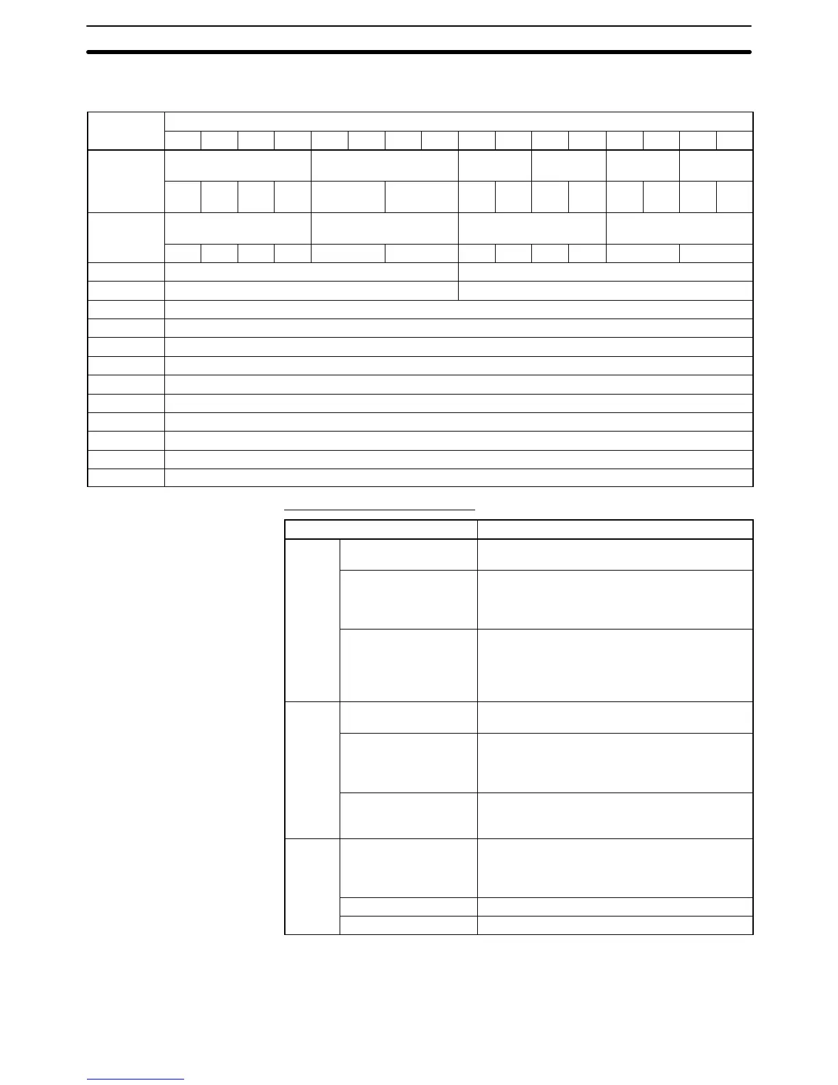
The following table shows the allocation of DM words and bits for both normal
and adjustment mode.
DM word
Bits
15 14 13 12 11 10 9 8 7 6 5 4 3 2 1 0
DM (m)
Not used. Ratio conversion use
designation
Not used. Use desig-
nation
Not used. Use desig-
nation
Loop 2 Loop 1 Input
2
Input
1
Out-
put 2
Out-
put 1
DM (m+1)
Not used. Input signal range set-
ting (See note 2.)
Not used. Output signal range set-
ting (See note 2.)
Input 2 Input 1 Output 2 Output 1
DM (m+2) Not used. Output 1: Output status when conversion stopped
DM (m+3) Not used. Output 2: Output status when conversion stopped
DM (m+4) Not used.
DM (m+5) Not used.
DM (m+6) Input 1: Mean value processing setting
DM (m+7) Input 2: Mean value processing setting
DM (m+8) Not used.
DM (m+9) Not used.
DM (m+10) Loop 1 (input 1 to output 1), A constant
DM (m+11) Loop 1 (input 1 to output 1), B constant
DM (m+12) Loop 2 (input 2 to output 2), A constant
DM (m+13) Loop 2 (input 2 to output 2), B constant
Set Values and Stored Values
Item Contents
Input
Use designation 0: Do not use.
1: Use.
Input signal range 00: –10 to 10 V
01: 0 to 10 V
10: 1 to 5 V/4 to 20 mA (See note.)
11: Same as for setting “10” above.
Mean value
processing setting
0000: No mean value processing
0001: Mean value processing for 2 buffers
0002: Mean value processing for 4 buffers
0003: Mean value processing for 8 buffers
0004: Mean value processing for 16 buffers
Output
Use designation 0: Do not use.
1: Use.
Output signal range 00: –10 to 10 V
01: 0 to 10 V
10: 1 to 5 V/4 to 20 mA (See note 2.)
11: Same as for setting “10” above.
Output status when
stopped
00: CLR 0 output
01: HOLD Hold output prior to stop
02: MAX Output maximum value of range
Loop
Ratio conversion use
designation
00: Do not use.
01: Use positive gradient conversion.
10: Use negative gradient conversion.
11: Same as for setting “10” above.
A constant 4 digits BCD (0 to 9999)
B constant 16-bit binary data
Note 1. For the DM word addresses, m = 1000 + 100 x unit number (Units #A to #F =
Unit numbers 10 to 15).
2. The I/O signal range of “1 to 5 V” or “4 to 20 mA” is switched according to the
input or output terminal connections.
DM Allocation Contents
 Loading...


