7120 Controller Hardware Overview
■
Fan Power Boards: The two fan power boards are FRUs and carry power to the system fan
modules. In addition, they contain fan module status LEDs and transfer I2C data for the fan
modules.
■
Storage Drive Backplane: The storage drive backplane is a FRU and includes the
connectors for the storage drives, as well as the interconnect for the I/O board, power and
locator buttons, and system/component status LEDs. The system has a 12-disk backplane.
Each drive has an LED indicator for Power/Activity, Fault, and Locate.
7120 CPU and Memory
The 7120 motherboard has 18 slots in two groups that hold industry-standard DDR3 DIMMs.
The standard memory configuration is 48GB, 6x8GB DDR-1333 low voltage (LV) DIMMS.
Following are the replaceable CPU and memory components of the 7120 system.
TABLE 46
7120 Controller Replaceable CPU and Memory Components
Part Number Description FRU/CRU
F371-4966-01 DIMM, 8GB, DDR3, 2RX4, 13 CRU
F371-4885-01 Intel E5620, 2.40G FRU
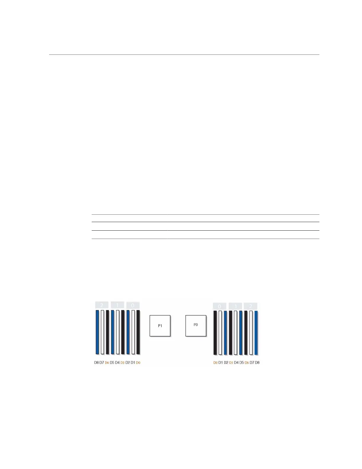
All sockets must be occupied by either a filler or a DDR3 DIMM. All DDR3 DIMMs must be
identical. DIMMs are pre-installed in P0 slots D1, D2, D4, D5, D7, and D8.
FIGURE 56
7120 Controller CPU and Memory Components
246 Oracle ZFS Storage Appliance Customer Service Manual • July 2016
 Loading...