- 62 - - 63 -
ORION
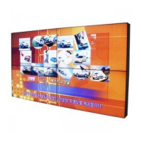
Innitely Expandable
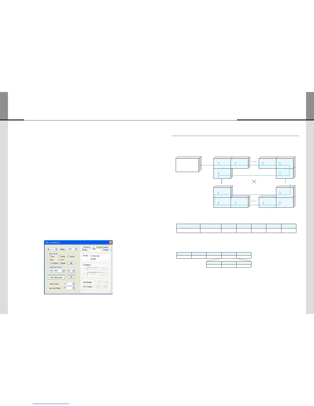
13) PIP (Picture In Picture)
• A variety of images can be displayed with the PIP function of DVI converter. To activate PIP,
click "PIP" in the Mode. The position of sub-picture can be controlled by clicking - / + buttons
increase or decrease the number or directly type in the numbers at Edit box.
• Various input sources can be used. To set the sub-input, click the sub-input combo box and
select sub-input.
• Main screen and sub-screen can be swapped with the PIP Swap function. Press "Set" button
at the right side of "PIP Swap." If you want to return to previous screen, press "Normal"
button at the right side of "PIP Swap."
• Mode : Normal mode - Normal screen without PIP (PIP Off)
PIP mode-Sub-screen is displayed at the lower right corner of the screen. (PIP On)
• Position : Horizontal - Adjust the horizontal location of PIP. Adjustable range 0~100
Vertical - Adjust the vertical location of PIP. Adjustable range 0~100
• Sub Input : Set the input for PIP. One of DVI, HDMI, HDSDI, PC, DTV, S-VIDEO, and VIDEO
can be selected for sub-input.
※ According to the main input, the sub-input can be restricted. If the main input is a digital input
such as DVI, HDMI or HD-SDI, the sub-input should be an analog input such as PC, DTV, S-VIDEO
or Video. If the main input is an analog input the sub-input should be a digital input.
• PIP Swap : OFF - Return to previous locations of swapped Main Source Input screen and
Sub Source Input screen.
ON - Exchange the locations of Main Source Input screen and Sub Source Input
screen.
1. Introduction
ThischaptercontainsthecommunicationprotocolbetweenLCDanditscontroldevicessuchascomputerforbetter
useoftheproduct.However,itdoesnotincludedetailedtechnicalmatters.Itratherfocusesonthebrieffunctional
explanationandcommunicationprotocol.
※Theconnectioncanbevariablebasedonenvironmentortheusers’intention.
<Communicationconnectiondiagram>
1.1. Communication Setting
Transmission &
Reception type
Connection type Baudrate Data Bits Parity Stop Bits Flow Control
Asynchronous Serial
Communication
Daisy Chain 115200 8 None 1 None
2. ProtocolFormat
2.1. Send To LCD
STX Command Length Data ETX
1 byte 1 byte 1 byte Variable 1 byte
ID Master Other Data
1 byte 1 byte N byte
- ThisishowtosendcommandstoLCD.OnlythesetofthedesignatedIDisworkingaccordingtothe"Command."
But,ifthe"ID"valueis"0",allMLCDsetsareworkingaccordingtocommandas"Broadcast".
- STX(0x02):Theinitialcode.ItmeansthebeginningofProtocol.(Fixedvalue)
- Command:Codeforactualoperation.(Variable)
- Length:thelengthof"Data"area.(Variable:0~255)
- Data:theareasfor"ID"andtheotherData(Variable)
- ID:ItisacodetodistinguishLCDsets.Itsrangeis"0"to"255".IftheIDis"0,"itmeansBroadcastcommand.(variable)
- Master(0x01):Thisisthescalercode.
- ETX(0x03):Theendofthecode.(Fixedvalue)
7. MSCS Protocol
MLCD
 Loading...