12
The PV (-) and BAT (-) terminals are connected internally. Only one negative wire may be needed to
connect to the (-) wire lugs if the PV - and BAT- conductors are bonded at the negative bus bar. See
Figures 2 and 3 for sample wiring diagrams. See Wire and Disconnect Sizing on page 80 for suitable
conductor/wire sizing.
NOTES:
• Each Charge Controller requires its own PV array. DO NOT PARALLEL Charge Controller PV+ and PV-
TERMINALS ON THE SAME ARRAY!
• An optional battery Remote Temperature Sensor (RTS) is recommended for accurate battery
recharging (only one RTS is needed for multiple OutBack Series Inverter/Chargers and Charge
Controller units when an OutBack HUB and a MATE are parts of the system). When one RTS is used,
it must be connected to the component plugged into the Port 1 of the HUB.
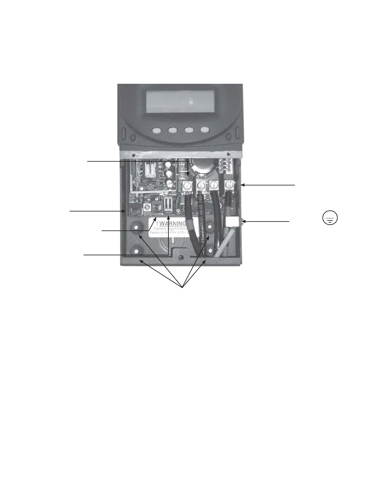
Figure 1 Charge Controller wiring compartment
Programmable
AUX Output Jack
(supplies up to
200mA @ 12 VDC
Battery Remote Temp
Sensor (RTS) RJ11 jack
Use up to 2 AWG
(33.6 mm
2
) wire
and torque to
35-inch pounds at
terminals.
MATE/HUB
RJ45 jack
Chassis/Equipment
Ground Lug
PV+ PV- BAT- BAT+
Wire Lugs
Screw holes for attaching Charge Controller
3. Charge Controller Wiring Connections
 Loading...