6
OUTBACK CHARGE CONTROLLER INSTALLATION GUIDELINES AND SAFETY
INSTRUCTIONS
This product is intended to be installed as part of a permanently grounded electrical system
as shown in the system con guration sections (see pages 12-15) of this manual. The following
important restrictions apply unless superseded by local or national codes:
• The negative battery conductor should be bonded to the grounding system at only one point in the
system. If a GFP is present, the battery negative and ground are not bonded together directly but are
connected together by the GFP device when it is on. All negative conductor connections must be
kept separate from the grounding conductor connections.
• With the exception of certain telcom applications, the Charge Controller should never be positive
grounded (see page 61, Applications Notes).
• The Charge Controller equipment ground is marked with this symbol:
• If damaged or malfunctioning, the Charge Controller should only be disassembled and repaired by a
quali ed service center. Please contact your renewable energy dealer/installer for assistance.
Incorrect reassembly risks malfunction, electric shock or re.
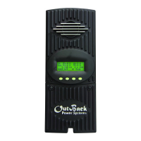
• The Charge Controller is designed for indoor installation or installation inside a weatherproof enclosure. It
must not be exposed to rain and should be installed out of direct sunlight.
For routine, user-approved maintenance:
• Turn o all circuit breakers, including those to the solar modules, and related electrical connections
before cleaning the air vents.
Standards and Requirements
All installations must comply with national and local electrical codes; professional installation
is recommended. NEC requires ground protection for all residential PV installations
DC and Battery-Related Installation Requirements:
• All DC cables must meet local and national codes.
• Shut o all DC breakers before connecting any wiring.
• Torque all the Charge Controller’s wire lugs and ground terminals to 35 inch-pounds (4 Nm).
• Copper wiring must be rated at 75° C or higher.
• Use up to 2 AWG (33.6 mm
2
) to reduce losses and ensure high performance of Charge Controller
(smaller cables can reduce performance and possibly damage the unit).
• Keep cables together (e.g., using a tie-wrap) as much as possible.
• Ensure both cables pass through the same knockout and conduit ttings to allow the inductive
currents to cancel.
• DC battery over-current protection must be used as part of the installation. OutBack o ers both
breakers and fuses for overcurrent protection.
 Loading...