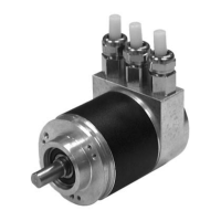
Absolute rotary encoder P**58
Installation
Subject to reasonable modifications due to technical advances. Copyright Pepperl+Fuchs, Printed in Germany
Pepperl+Fuchs Group • Tel.: Germany +49 621 776-0 • USA +1 330 4253555 • Singapore +65 67799091 • Internet http://www.pepperl-fuchs.com
Date of issue 01/15/04
7
The bus is not correctly terminated unless the rotary encoder is mounted on the
connection hood. If the encoder needs to be replaced while the system is in operation,
we recommend using a separate active bus termination.
After the address is set on the hardware side and the power terminating resistor has
been switched into the circuit if necessary, the rotary encoder can be placed in
operation.
2.2 Connection of signal and power supply lines
When the terminating resistor is turned on, the rest of the bus (Bus
Out) is disconnected.
Terminal Explanation
⊥ ground connection for power supply
B (left) data line B (pair 1), Bus In
A (left) data line A (pair 1), Bus In
(-) 0 V
(+) 10 V ... 30 V
B (right) data line B (pair 2), Bus Out
A (right) data line A (pair 2), Bus Out
(-) 0 V
(+) 10 V ... 30 V
Power supply lines only need to be connected once (no matter to
which terminals). When the terminating resistor is turned on, the rest of
the bus (Bus Out) is disconnected.
Note
A
B
AB
-
+-+
Bus Out
Bus In
Note

 Loading...