Service Modes, Error Codes, and Fault Finding
EN 22 TPN16.3E LA5.
2016-Oct-28
back to
div. table
Table 5-1 SAM mode overview
How to Navigate
• In the SAM menu, select menu items with the UP/DOWN
keys on the remote control transmitter. The selected item
will be indicated. When not all menu items fit on the screen,
use the UP/DOWN keys to display the next/previous menu
items.
• With the “LEFT/RIGHT” keys, it is possible to:
– (De) activate the selected menu item.
– (De) activate the selected sub menu.
– Change the value of the selected menu item.
• When you press the MENU button once while in top level
SAM, the set will switch to the normal user menu (with the
SAM mode still active in the background).
• Press the following key sequence on the remote control
transmitter: “062596” directly followed by the “Home/Menu”
button to switch to (do not allow the display to time out
between entries while keying the sequence).
How to Store SAM Settings
To store the settings changed in SAM mode (except the
RGB Align settings), leave the top level SAM menu by using
the POWER button on the remote control transmitter or the
television set. The mentioned exceptions must be stored
separately via the STORE button.
How to Exit SAM
Use one of the following methods:
• Switch the set to STANDBY by pressing the mains button
on the remote control transmitter or the television set.
• Via a standard RC-transmitter, key in “00” sequence.
Note: When the TV is switched “off” by a power interrupt while
in SAM, the TV will show up in “normal operation mode” as
soon as the power is supplied again. The error buffer will not be
cleared.
5.1.3 Contents of the Factory mode:
Purpose
• To perform extended alignments.
Specifications
• Displaying and or changing Panel ID information.
• Displaying and or changing Tuner ID information.
• Error buffer clearing.
• Various software alignment settings.
• Testpattern displaying.
• Public Broadcasting Service password Reset.
•etc.
How to Activate the Factory mode
To activate the Factory mode, use the following method:
• Press the following key sequence on the remote control
transmitter: from the “menu/home” press “1999”, directly
followed by the “Back/Return” button. Do not allow the
display to time out between entries while keying the
sequence.
After entering the Factory mode, the following items are
displayed,
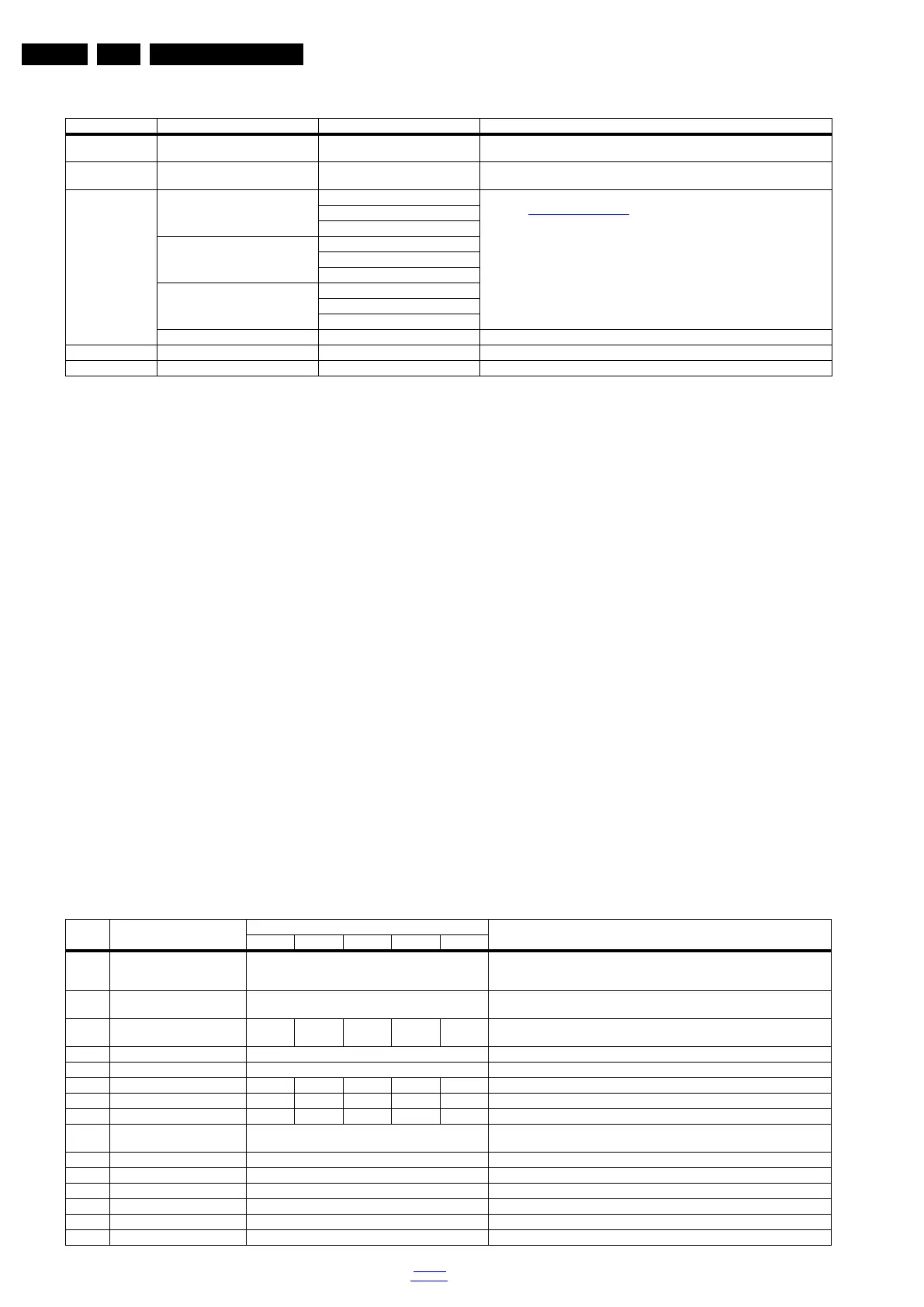
Table 5-2 Factory mode overview
Main Menu Sub-menu 1 Sub-menu 2 Description
System Information Op Hour e.g. 00082 This represents the life timer. The timer counts normal operation hours, but does not
count Stand-by hours.
Clear Press [OK] to clean the Error Codes
immediately
Erases the contents of the error buffer. Select this menu item and press the MENU
RIGHT key on the remote control. The content of the error buffer is cleared.
RGB Align Warm R Gain To align the White Tone. See
paragraph 6.3 Software Alignments in the Alignments section for a detailed
description
G Gain
B Gain
Normal R Gain
G Gain
B Gain
Cool R Gain
G Gain
B Gain
Store Store the RGB value
Upload to USB Copy Channel List to USB To upload several settings from the TV to an USB stick
Download from USB Copy Channel List from USB To download several settings from the USB stick to the TV
Item Item value
Default value
Description22" 24" 32" 43" 49"
0 F/W VERSION Press OK Displays the software versions of the supplier, Flash PQ, Smart Picture,
BL Dimming, Source Meter, the Picture Quality checksum, the Dimming library, the
Source meter library, the Flash AQ, MCU and OAD software versions.
1 Board ID 715G8232_3in1 Dispaly the Board ID; be careful changing this, it can result in not correct displaying
the screen!
2 PANEL_ID 8 9 4 6 7 Displays and changes the Panel ID with the left and right cursor; be careful
changing this, it can result in not correct displaying the screen!
3 DB COPY TV to USB Press OK DB COPY TV to USB
4 DB READ USB to TV Press OK DB READ USB to TV
5 CLR_TEMP_R 128 74 116 100 128 Red colour temperature setting
6 CLR_TEMP_G 128 80 119 112 128 Green colour temperature setting
7 CLR_TEMP_B 128 128 128 128 128 Blue colour temperature setting
8 AUTO_COLOR Press OK PC: any pattern that has black and white, YPbPr: SMPTE bar (colour bar), any
timing.
9 ADC_GAIN_R 0 Red ADC gain
10 ADC_GAIN_G 0 Green ADC gain
11 ADC_GAIN_B 0 Blue ADC gain
12 ADC_OFFSET_R 0 Red ADC offset
13 ADC_OFFSET_G 0 Green ADC offset
14 ADC_OFFSET_B 0 Blue ADC offset
 Loading...