Wiring the outputs and inputs
106377_en_04 PHOENIX CONTACT 33 / 68
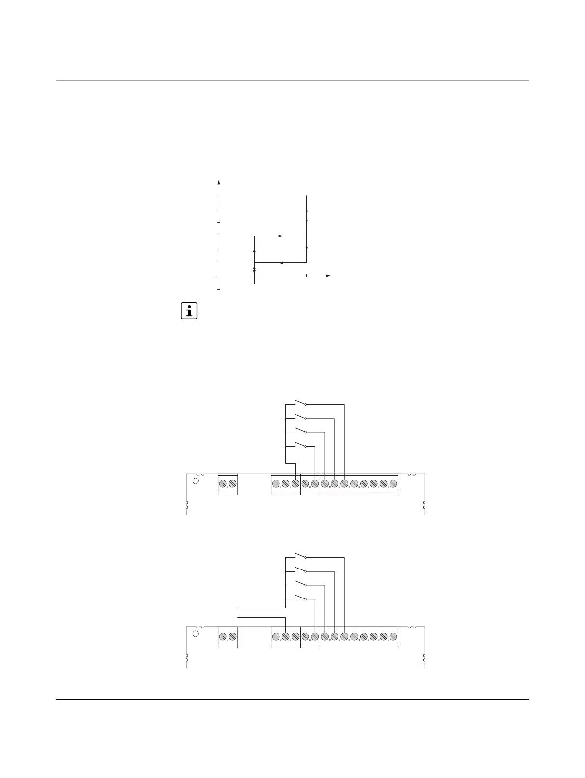
6.2 Inputs
The inputs are designed as voltage dividers for a voltage from 0 V to +15 V. A current of
< 1 mA flows across the resistor network at 12 V. Logic 0 is reliably detected at a voltage of
0 V to +3 V. Logic 1 is reliably detected at a voltage of +9 V to +15 V.
Figure 6-4 Assignment of the logic states to the voltages
The function of the digital inputs can be configured via Modbus/RTU. For details,
please refer to “Modbus description” on page 53.
The circuits of the inputs are only examples. The inputs with switches can be supplied by
the internal voltage source as well as by an external 12 V voltage source which uses GND
as the common reference point. The inputs can also be controlled by an external higher-
level controller with 12 V outputs. Here too, GND is used as the common reference point.
Figure 6-5 Inputs at switches with internal supply
Figure 6-6 Inputs at switches with external supply
Power
L
N
PE
IO
GND
12 V
12 V a
EN
XR
ML
CCR
IN
OUT
ERR
CHG
CON
Power
L
N
PE
IO
GND
12 V
12 V a
EN
XR
ML
CCR
IN
OUT
ERR
CHG
CON
GND
12 V DC

 Loading...


