EV Charge Control Basic
40 / 68
PHOENIX CONTACT 106377_en_04
7.6 Charging current control via analog CCR signal
The digital CCR input can be reconfigured to function as an analog input (see
Table 9-2 “Register assignment”).
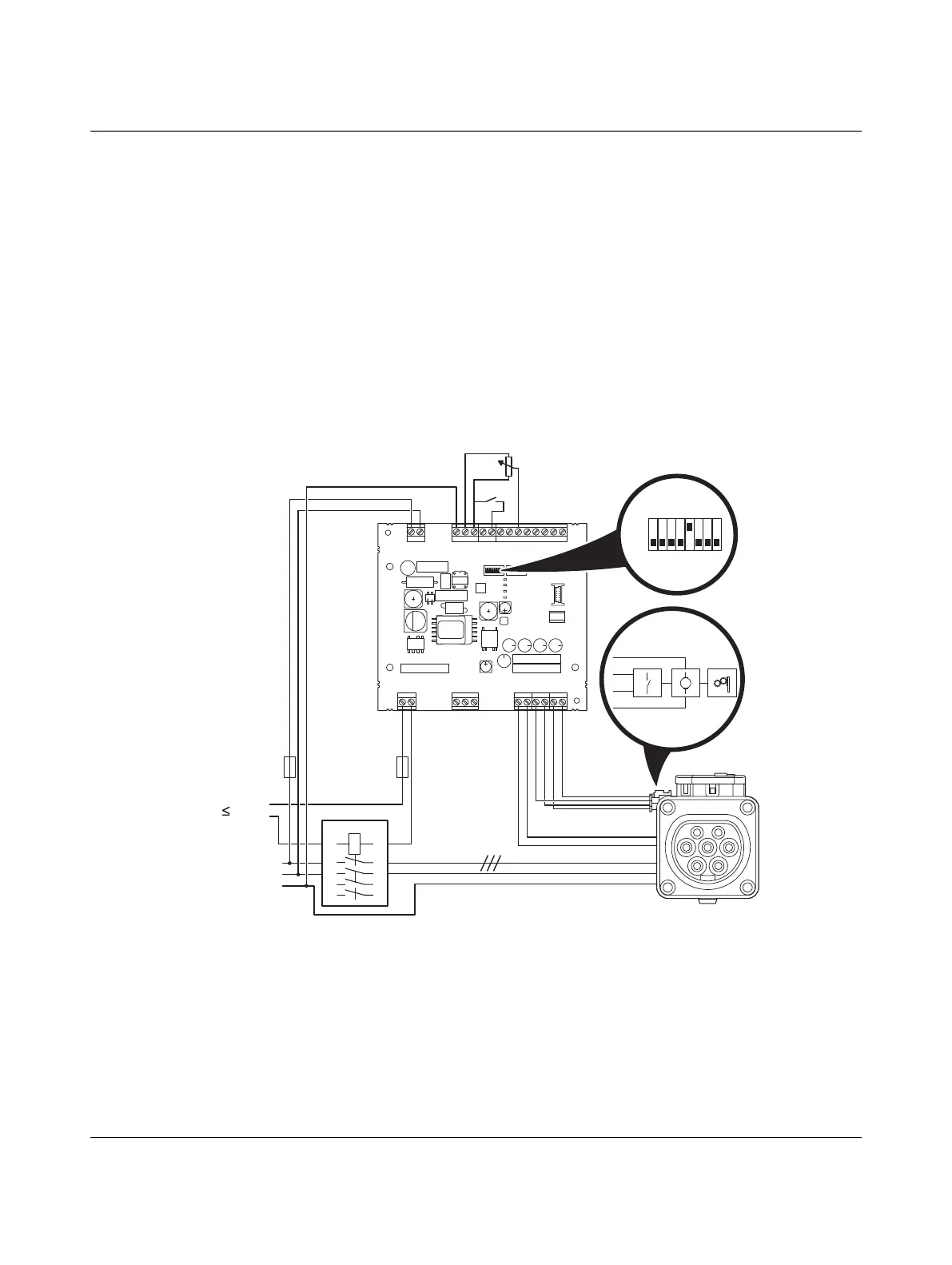
Figure 7-6 Connection example 6
S1/DIP 1 = OFF Charging station with Infrastructure Socket Outlet
S1/DIP 5 = ON Charging current preset to 32 A
Locking is carried out if a vehicle is detected.
The charging process starts if the locking feedback is available, switch k1 is closed, and
status C is present.
When changing the voltage at the analog CCR input, e.g., using a potentiometer, the max-
imum charging current can be adjusted.
L
N
PE
GND
12V
12Va
EN
XR
ML
CCR
IN
OUT
ERR
CHG
CON
C1
C2
A
B
SG
CP
PP
L1D
L2D
L0+
L0-
IO
Relay
R 485S
Outlet
Power
PWR
S1 S2
CON
ERR
CHR
M
RD
GN
YE
BN
N
PE
L, L1-L3
230V
1
3 5
24
6
1A
2A
7
8
1
32 A
S1
0
k1
EV-T2M3SE12-3AC...
EV-CC-AC1-M3-CBC-...,
connection of case B

 Loading...


