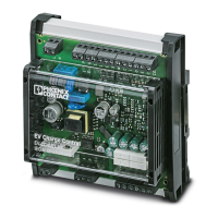
Properties of the charging controller
106377_en_04 PHOENIX CONTACT 5 / 68
1 Properties of the charging controller
The EV Charge Control Basic charging controller is exclusively used to control and monitor
the charging of electric vehicles on the 3-phase AC power grid in charging mode 3 accord-
ing to IEC 61851-1, AC level 2 according to SAE J1772, and mode 3 according to
GB/T 18487.1.
The charging controller is integrated in a defined charging infrastructure which is perma-
nently connected to the power grid.
The charging controller is designed to control the switching element which is used to estab-
lish the connection between the power grid and the electric vehicle. It has a communication
interface via which status data can be read and control signals can be written. The charging
controller monitors the Control Pilot and Proximity Plug signals.
The Control Pilot signal (CP) has the following functions, for example:
– Detection of the protective conductor connection
– Detection of the vehicle status: vehicle not connected, vehicle connected, vehicle
ready for charging, ventilation required, error
– Transmission of the charging controller status: ready, not ready, error
– Specification of the maximum available charging current for the vehicle via a PWM sig-
nal
The charging controller detects the inserted charging connector and the current carrying ca-
pacity of the charging connector and charging cable via the Proximity Plug signal (PP).
Resistor coding in the charging connector is used for this purpose.
The charging controller can be used to activate or deactivate the charging connector locking
in the charging station depending on the status.
As an option, the charging process can also be influenced and monitored via the existing
communication interface.
Technical features – Evaluating and controlling the Control Pilot signal
– Monitoring the connection to protective earth ground (PE)
– Evaluating the Proximity Plug signal
– Controlling the charging contactor and locking actuators
– Maximum charging current that can be configured: 16 A, 20 A, 32 A, 63 A
– RS-485 communication interface/Modbus/RTU (slave)
– Digital inputs and outputs, can be configured
– Controlling and enabling the charging controller locking in the event of a mains failure
– Temperature range: -35°C ... +70°C
– Altitude: < 2000 m
– Versions available for charging stations with an infrastructure socket outlet (connection
of case B) and vehicle connector (connection of case C)
– Available either as PCB or with housing for DIN rail mounting

 Loading...


