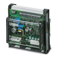
EV Charge Control Basic
4 / 68
PHOENIX CONTACT 106377_en_05
7 Connection examples ..............................................................................................................35
7.1 Charging enabled with local release.................................................................... 35
7.2 Charging enabled with local release and status indication via external LEDs...... 36
7.3 Charging enabled with local release and charging current reduction................... 37
7.4 Charging enabled with local release and locking................................................. 38
7.5 Charging enabled via Modbus............................................................................. 39
7.6 Charging current control via analog CCR signal .................................................. 40
7.7 Charging contactor monitoring ............................................................................ 42
7.8 Connection to a residual current monitoring device............................................. 44
8 Flow charts for the charging process .......................................................................................47
8.1 Charging sequence 1 .......................................................................................... 47
8.2 Charging sequence 2 .......................................................................................... 48
8.3 Charging sequence 3 .......................................................................................... 49
8.4 Charging sequence 4 .......................................................................................... 50
8.5 Charging sequence 5 .......................................................................................... 51
8.6 Charging sequence 6 .......................................................................................... 52
9 Modbus description .................................................................................................................53
9.1 Modbus register types ......................................................................................... 53
9.2 Register assignment............................................................................................ 54
9.3 Function assignment of output registers.............................................................. 63
A Appendixes...............................................................................................................................65
A 1 List of figures ....................................................................................................... 65

 Loading...


