Connections, indicators, configuration switches
106377_en_04 PHOENIX CONTACT 9 / 68
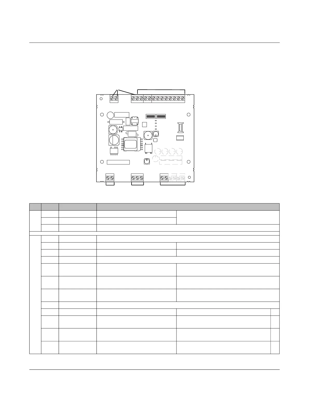
2 Connections, indicators, configuration switches
2.1 Connections
Figure 2-1 Connections
L
N
PE
GND
12V
12Va
EN
XR
ML
CCR
IN
OUT
ERR
CHG
CON
C1
C2
A
B
SG
CP
PP
LD1
LD2
L0+
L0-
IO
Relay
R 485S
Outlet
Power
PWR
S1 S2
CON
ERR
CHR
1
2
345
Table 2-1 Connections
No. Name Meaning Description
1 L Line Phase, power grid 100 V AC ... 240 V AC (L-N)
N Neutral Neutral conductor, power grid
PE Protective Earth Functional earth ground, connected to protective earth ground
2 GND Ground System ground, connected to protective earth ground
12V Power Output 12 V DC, max. 500 mA
12Va Auxiliary Power Supply input of the outputs 5 V DC ... 30 V DC
EN Enable Digital input, can be configured, enable charging process
XR External Re-
lease
Digital input, can be configured,
charging station availability
Activation via S1/DIP 2, can be configured
ML Manual Lock Digital input, can be configured,
manual locking
Activation via S1/DIP 3, can be configured
CCR Charge Current
Reduction
Digital input, charging current limit Depending on the default settings by
S1/DIP 5 + 6
IN Auxiliary Input Reserved for future expansions
OUT Auxiliary Out Digital output, can be configured Default: output can be set via Modbus *
ERR Error Digital output, can be configured Default: set when errors occur
Error or status E or status F
*
CHG Charging Digital output, can be configured Default: set when the charging contactor is
actuated
*
CON Connect Digital output, can be configured Default: set when a vehicle is connected to
the charging controller
*