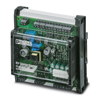
EV Charge Control Basic
44 / 68
PHOENIX CONTACT 106377_en_04
7.8 Connection to a residual current monitoring de-
vice
As of firmware version 1.2.0
NOTE: Notes on wiring the EV-RCM
To ensure that the charging contactor switches off independently in the event of a
6 mA DC residual current, please observe this installation note. The EV-RCM must be
connected in series with the charging controller (terminal blocks C1 and C2) and the
charging contactor (1A/2A) using the terminal blocks (13/14 and 23/24) (see
Figure 7-9 on page 45).
S1/DIP 1 = OFF Charging station with Infrastructure Socket Outlet
S1/DIP 2 = OFF The XR input is evaluated in a modified way according to Modbus register 4011 (see
Table 7-3 on page 45).
Locking is carried out if a vehicle is detected.
The charging process starts if the locking feedback is available and status C is present.
The charging process is interrupted if the EV-RCM residual current monitoring device de-
tects a residual current of 6 mA DC. The charging controller then changes to the F status.
Two EV-RCM differential current monitoring devices are available:
– EV-RCM-C1-AC30-DC6, 1622450 (1 channel)
– EV-RCM-C2-AC30-DC6, 1622451 (2 channels)
The charging connector unlocks with a time delay and can be removed from the Infrastruc-
ture Socket Outlet.
If the charging connector has been removed, the charging controller resets the EV-RCM. As
soon as the EV-RCM has been reset, the charging controller is ready for charging again
(status A).
A selftest on the EV-RCM is performed following every charging process.

 Loading...


