Connection examples
106377_en_04 PHOENIX CONTACT 45 / 68
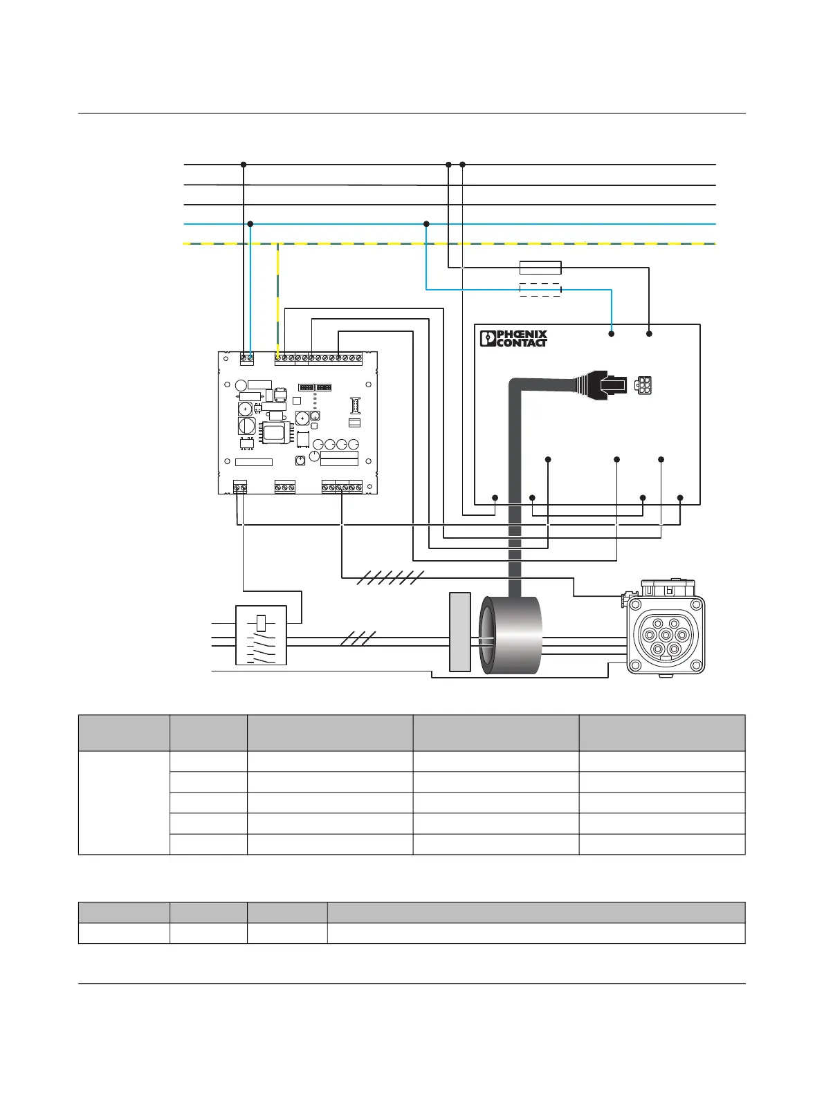
Figure 7-9 Connection example 8 (with EV-RCM-C1-AC30-DC6, 1622450)
L
N
PE
GND
12V
12Va
EN
XR
ML
CCR
IN
OUT
ERR
CHG
CON
C1
C2
A
B
SG
CP
PP
L1D
L2D
L0+
L0-
IO
Relay
R 485S
Outlet
Power
PWR
S1 S2
CON
ERR
CHR
L1
L2
L3
PE
N
13 14 23 24
ERR
Test
GND
A1 A2
RCM
RCD TYP A
F
F
1
3 5
24
6
1A
2A
7
8
L,L1-L3
N
PE
N
Table 7-3 Function activation for connecting the EV-RCM residual current monitoring device at input XR
Address Value Function Automatic resetting of
error messages
Automatic EV-RCM
device test
4011 0 Deactivated – –
1 Activated Active Active
2 Activated Inactive Active
3 Activated Active Inactive
*
4 Activated Inactive Inactive
*
*
The device test can also be carried out manually or from a higher-level controller.
Table 7-4 Device configuration example for connecting the EV-RCM residual current monitoring device
Address Value Unit Explanation
5500 38 – Triggering of EV-RCM device test activated at output OUT

 Loading...


