EV Charge Control Basic
36 / 68
PHOENIX CONTACT 106377_en_04
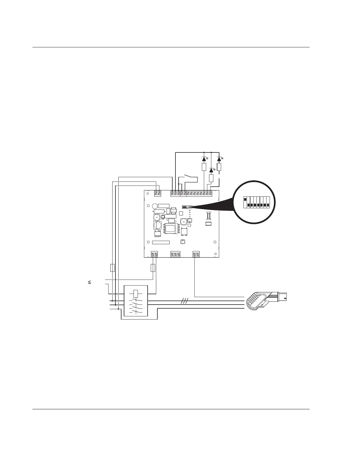
7.2 Charging enabled with local release and status in-
dication via external LEDs
Figure 7-2 Connection example 2
S1/DIP 1 = ON Charging station with Vehicle Connector
Status indication via external LEDs
The charging process starts if switch k1 is closed and status C is present.
– LED 1 is on when the vehicle is connected to the charging station.
– LED 2 is on during the charging process.
– LED 3 is on in the event of an error.
L
N
PE
GND
12V
12Va
EN
XR
ML
CCR
IN
OUT
ERR
CHG
CON
C1
C2
A
B
SG
CP
PP
L1D
L2D
L0+
L0-
IO
Relay
R 485S
Outlet
Power
PWR
S1 S2
CON
ERR
CHR
N
PE
L, L1-L3
230 V
1
3 5
24
6
1A
2A
7
8
k1
LED1
LED2
LED3
1
S1
0
EV-CC-AC1-M3-CC-...,
connection of case C
EV-T2M3C-...
EV-T1M3C-...

 Loading...


