Modbus description
106377_en_04 PHOENIX CONTACT 63 / 68
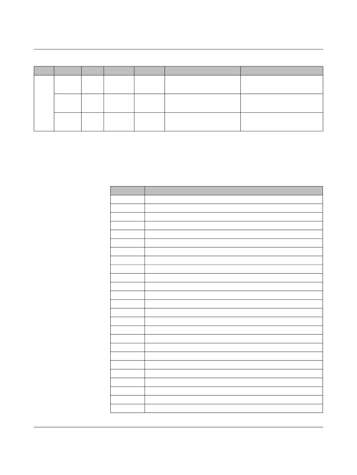
9.3 Function assignment of output registers
The digital inputs can be assigned different functions by entering values according to
Table 9-3 to registers 5500 – 5503.
Hold-
ing
26002 16 bits Read Volatile Evaluating input ML as analog
input
Integer, 1 x 16 bits
Standardized to mV
26003 16 bits Read Volatile Evaluating input CCR as ana-
log input
Integer, 1 x 16 bits
Standardized to mV
26004 16 bits Read Volatile Evaluating input IN as analog
input
Integer, 1 x 16 bits
Standardized to mV
Table 9-2 Register assignment
Type Address Value Access Memory Function Coding
Table 9-3 Function assignment of output registers for the digital outputs
Value Function
0 Control from the assigned output register (23000 – 23003)
1 Charging controller in status A
2 Charging controller in status B
3 Charging controller in status B and PWM ON
4 Charging controller in status B and PWM OFF
5 Charging controller in status C
6 Charging controller in status D
7 Charging controller in status E
8 Charging controller in status F
9 Charging controller in status A or B
10 Charging controller in status A or B and PWM ON
11 Charging controller in status A or B and PWM OFF
12 Charging controller in status A - C
13 Charging controller in status A - B or D
14 Charging controller in status A - D
15 Charging controller in status E - F
16 Charging controller in status C or D
17 PWM ON
18 Charging controller has detected a valid PP value
19 Charging controller has detected an invalid PP value
20 Charging controller has detected a 13 A connector at PP
21 Charging controller has detected a 20 A connector at PP
22 Charging controller has detected a 32 A connector at PP
23 Charging controller has detected a 63 A connector at PP
24 Charging controller has detected a 13 A or 20 A connector at PP