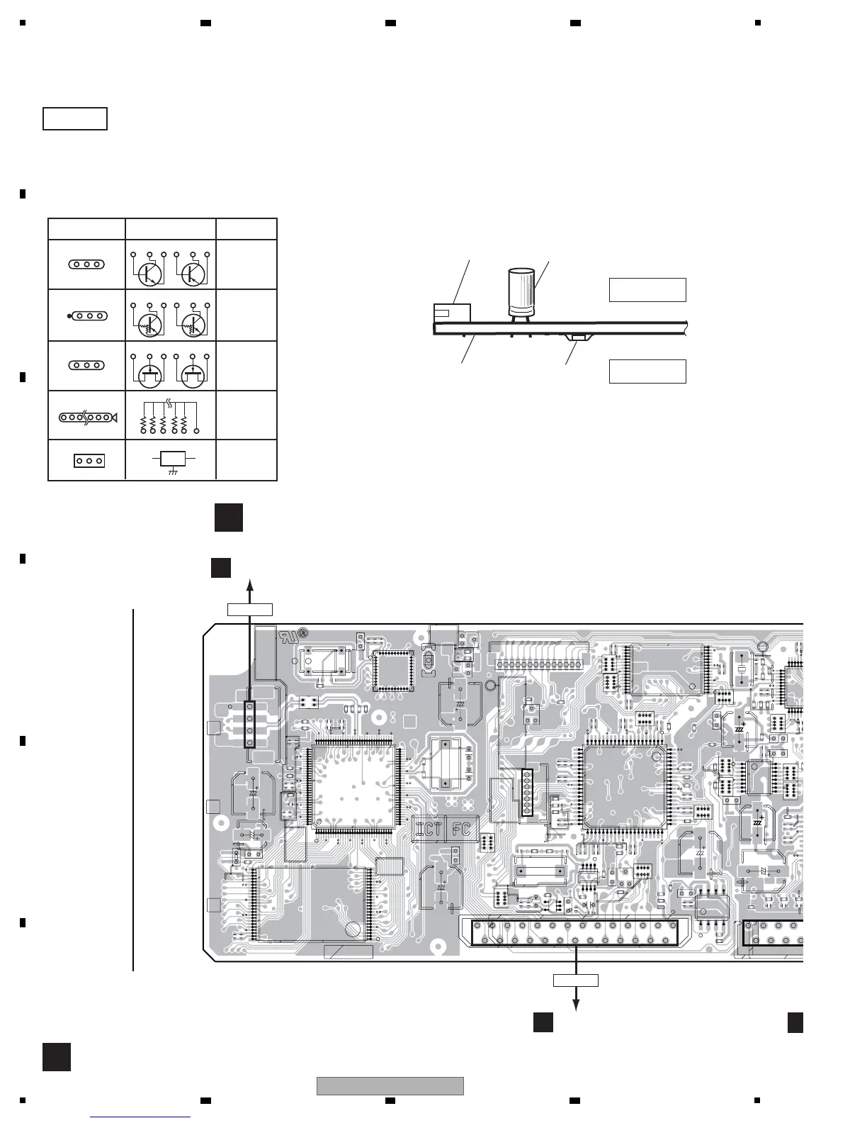
11. PCB CONNECTION DIAGRAM
2/2
A
A
AWX8979
R210
R211
R407
R408
L261
L262
R218
R219
CN201
L462
R418
R225
R419
R226
R227
R228
CN401
R421
R422
R423
IC181
R431
C201
R432
C202
C203
C204
L481
C205
C206
C207
C208
C209
C210
R444
C214
R251
R445
C215
R252
R446
C216
R253
R447
C217
R254
C218
R255
C219
X402
C413C414
C221
C222
C223
C224
R261
C225
R262
C226
R263
C227
R264
C228
R265
C229
C423
C230
C424
C425
R462
C426
R463
C427
C428
R271
C429
R273
C430
R279
C432
C433
C434
C435
C436
C437
C443
R481
C251
C252
C261
C455
C262
C263
C264
C265
C266
C267
C268
C271
X261
C272
C273
C467
C274
C468
C275
C276
IC201
C481
L121
IC401
C482
C483
C485
C486
X481
Q341
R303
R307R308
R30
IC251
R315
R123
IC261
IC262
R130R131
R132
L181
IC462
R136
R137
R138
IC271
R139
R335
L191
C301
C30
C303
C304
C305
C307C308
R345
C3
IC481
C121
C129
C130
C131
X121
C132
C133
C134
C135
C136
R181
R182
R183
R185
R186
R187
R41
R42
R43
R44
R45
R194
R196
Q201
Q401
Q402
L202
C181
C182
L403
L404
CN4
IC121
CN7CN8
JH501
R201
L442
R202
L251
R208
LF
A30C5/C7
[[ G ]]
AWX9163
AWX9164
AWX
20
5
1
15
10
1
5151
0201
1
525151
0201
E
E
1 5 10 15 20 25 30
35 40 45 50 55 60
65 70 75 80
859095
100 105 110 115 120 125
15
20
15 10 15 20
25
30
35
40
45505560
65
70
75
80
1
15
1
1
E
1
1
1
E
1
1
1
1
1
5
1
1
5
1
5
10
15
20
25
30
35
40
45
1
5
1
15 1015
202530
1
1
1
15 10
15 20
25 30
35 40
15
1015
1
11
1
20
25 30 35
40
1
5
1
IC171
IC181
IC201
IC401
Q341
IC251
IC261
IC262
IC462
IC271
IC1
IC2
IC481
Q201
Q401
Q402
Q
IC101
IC301
IC121
IC
IC122
DSP&USB ASSY
B
B
SIDE A
C
CN112
A
CN8
CN953
T
CN401
NOTE FOR PCB DIAGRAMS :
1. Part numbers in PCB diagrams match those in the schematic
diagrams.
2. A comparison between the main parts of PCB and schematic
diagrams is shown below.
3. The parts mounted on this PCB include all necessary parts for
several destinations.
For further information for respective destinations, be sure to
check with the schematic diagram.
4. View point of PCB diagrams.
Symbol In PCB
Diagrams
Symbol In Schematic
Diagrams
Par t Name
B
C
E
D
D
G
G
S
S
B
C
E
BCE
DGS
BCEBCE
BCE
Transistor
Transistor
with resistor
Field effect
transistor
Resistor array
3-terminal
regulator
Capacitor
Connector
P.C.Board
Chip Part
SIDE A
SIDE B
 Loading...