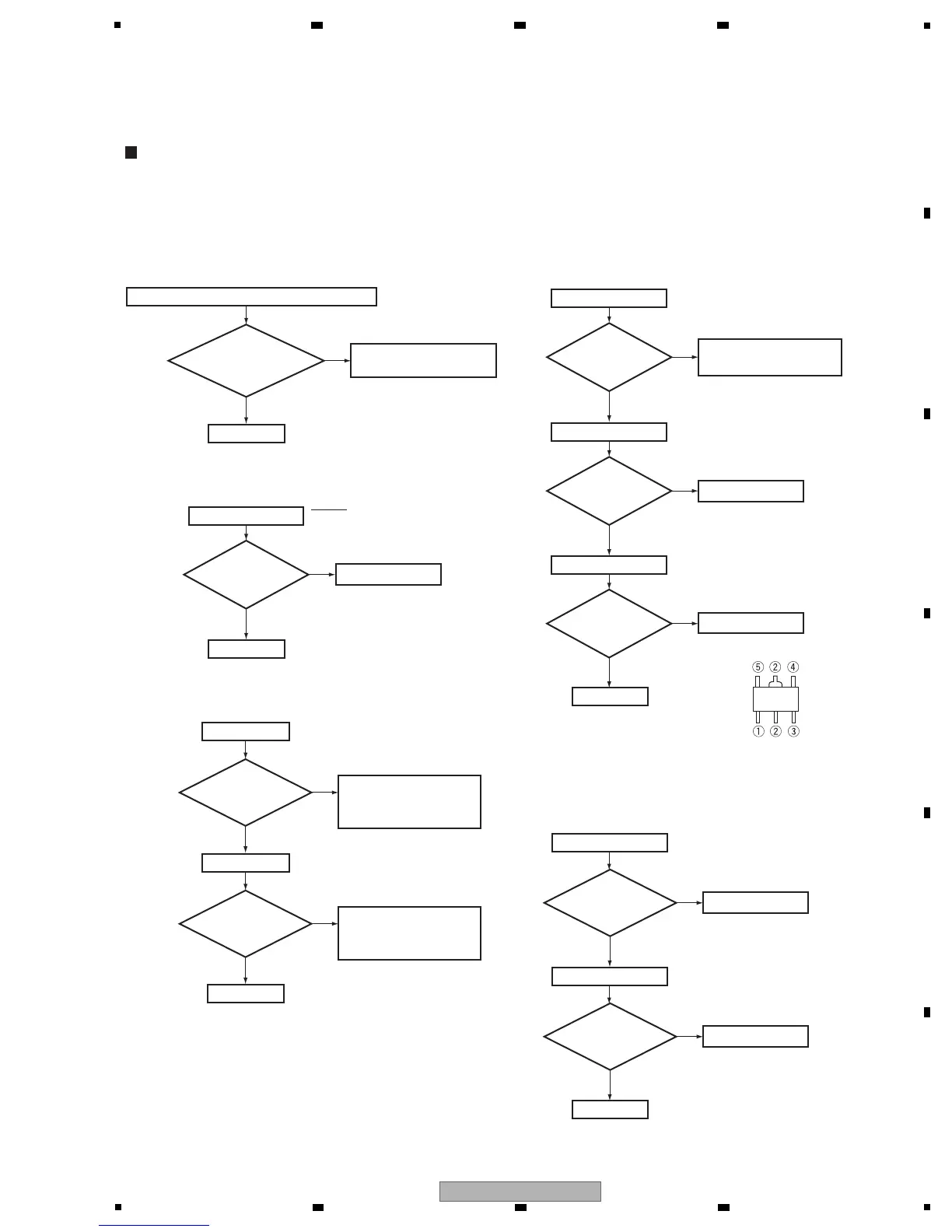
5. DIAGNOSIS
• When a sound is not out in the multi-CH signal playback mode or surround mode with the COAX, OPT, USB or HDMI input.
(SurroundBack is not output by setting.)
• Suppose CR to be normal contact and that is not damaged.
• This shows failure analysis of DSP Block.
Step 4: 3 V to 5 V conversion
Step 1: MUTE pin
IC351
Do
convert 3 V into
5 V for input?
Replace IC201.
Replace IC1.
Replace IC2.
To Step 2
To Step 4
To Step 5
Step 0: Preliminary confirmation
Confirm the following items before checking
Do screws
of COAX Jack
securely tighten
?
Tighten screws securely.
No
Ye s
To Step 1
IC201 (Pin 54)
Is the
voltage of output
signal 0 V
?
No
Replace IC351.
No
Ye s
MUTE
Troubleshooting for all destination
[1] DSP TROUBLESHOOTING
Step 3: Regulator IC
Check the IC1 and
REGULATOR Assy.
IC1 (Pin 4)
Is the
voltage of around
5 V to 5.3 V
input?
No
Ye s
(to chassis)
IC2 (Pin 5)
Is the
voltage of 1.25 V
output?
No
(to chassis)
IC1 (Pin 5)
Is the
voltage of 3.3 V
output?
No
Ye s
Ye s
Ye s
IC341
Do
convert 3 V into
5 V for input?
Replace IC341.
No
Ye s
(to chassis)
Part shape and Pin arrangement
of IC1 and IC2
Step 2: BtoB connector and FFC
CN1, CN2
Are the
connectors securely
inserted?
Turn the power off and
insert the connectors
securely.
No
Ye s
CN3
Is the
FFC securely
inserted?
Turn the power off and
insert the connectors
securely.
No
Ye s
To Step 3
BtoB connector
FFC
 Loading...