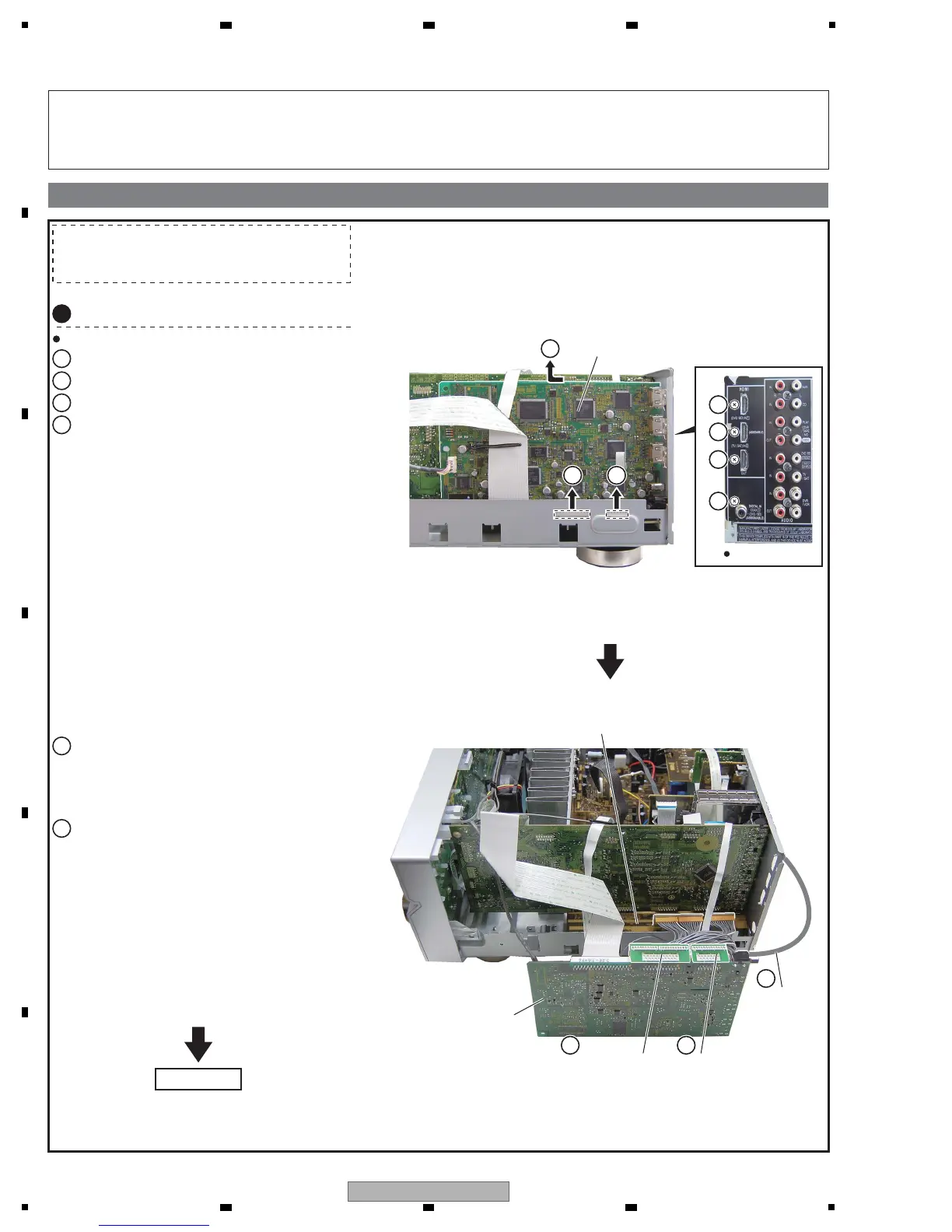
7. DISASSEMBLY
Remove the three screws.
HDMI&DSP&USB Assy
HDMI&DSP&USB
Assy
POWER PACK Assy
Extension jig cable
(GGD1485)
Extension jig cable
(GGD1483)
Ground line
Diagnosis of HDMI
1
Remove the bonnet by removing the six screws.
1
Remove the one screw.
2
Disconnect the two connectors.
3
Remove the HDMI&DSP&USB Assy.
4
Connect the two extension jig cables.
GGD1483
(HDMI&DSP&USB CN1 <=> POWER PACK CN805)
GGD1485
(HDMI&DSP&USB CN2 <=> POWER PACK CN806)
5
Connect the ground line.
(HDMI&DSP&USB COAX terminal <=> Rear panel,
One of the three HDMI terminals <=> Rear panel)
6
1
1
1
2
3 3
4
5 5
6
Note 1: Even if the unit shown in the photos and illustrations in this manual may differ from your product, the procedures
described here are common.
Note 2: For performing the diagnosis shown below, the following jigs for service are required:
• Extension jig cables : GGD1483, GGD1485
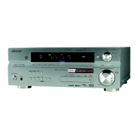
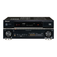
Rear view
Caution:
Heatsink section in work becomes hot, and be
careful with it.
For VSX-918V
Diagnosis
 Loading...