BRAKES 4 - 11
November 2007 GEM Service Manual
BRAKE PEDAL ASSEMBLY
DESCRIPTION
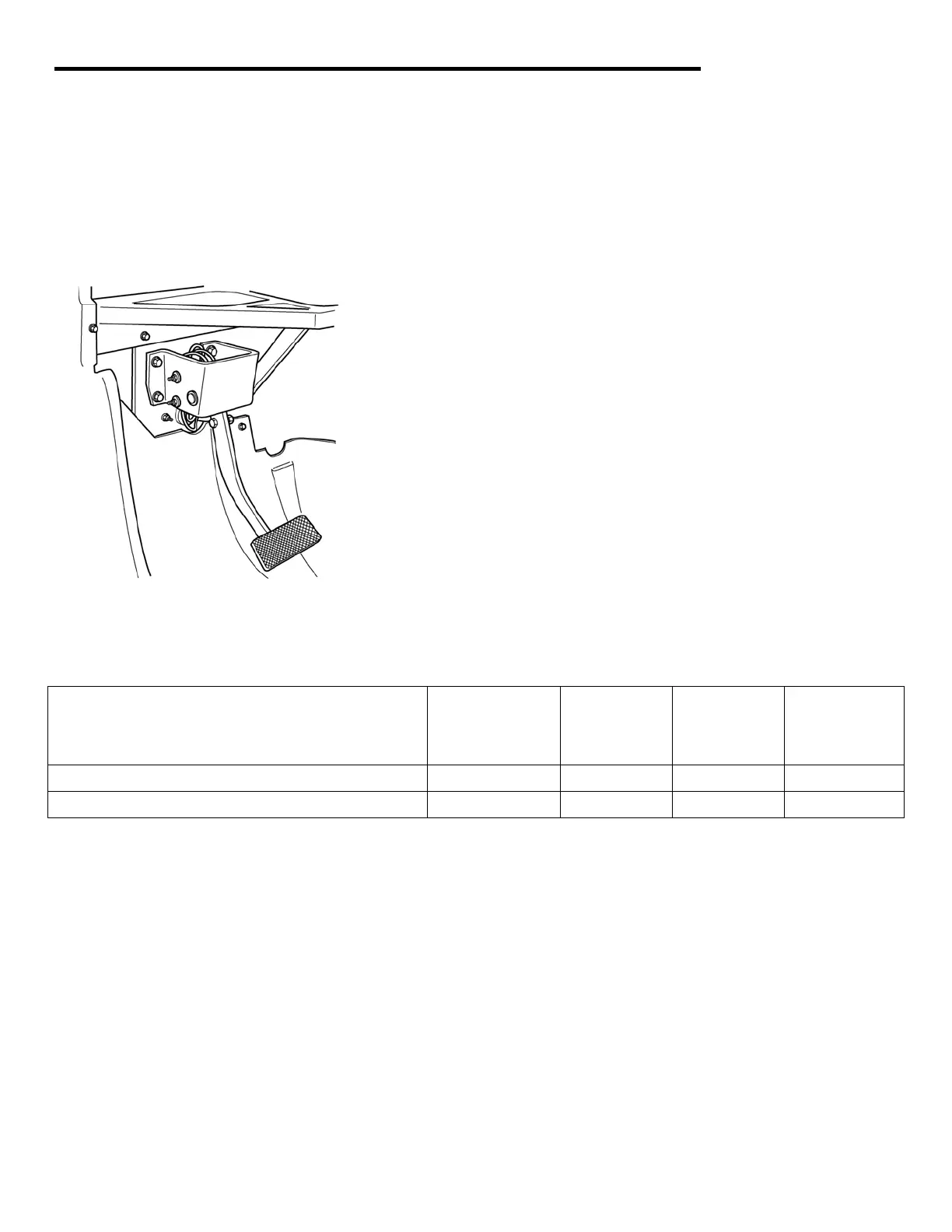
The brake pedal assembly is mounted on the dash
support frame. It consists of the brake pedal,
bracket, push rod, and pedal return spring.
Fig. 7 Brake Pedal Assembly
OPERATION
The brake pedal pivots on a shaft mounted on the
bracket. Foot pressure causes downward motion of
the pedal, forcing a push rod against a piston in the
master cylinder. When foot pressure against brake
pedal is released, a return spring forces the pedal
(and push rod) back to its original position, relieving
pressure in master cylinder.
REMOVAL
1. Remove upper and lower dash panels. See
Dash Upper Panel and Dash Lower Panel in
Body section.
2. Remove the four bolts attaching pedal
assembly to dash support frame
3. Remove the brake pedal assembly.
TORQUE SPECIFICATIONS
Description Thread Size Use
Loctite®
242
Inch-
Pounds
Foot
Pounds
Brake pedal assembly to frame
5/16 – 18 NO 225 ---
Brake pedal to push rod
3/8 - 16 NO --- 30
INSTALLATION
1. Position brake pedal assembly on dash support
frame, making sure push rod passes
through\bellows and properly engages master
cylinder piston.
2. Install pedal assembly to dash support frame
with four mounting bolts. Tighten to 225 in-lb.
3. Install upper and lower dash panels. See Dash
Upper Panel and Dash Lower Panel in Body
section.
 Loading...