ELECTRICAL 5 - 38
November 2007 GEM Service Manual
LIQUID CRYSTAL DISPLAY
(LCD)
DESCRIPTION
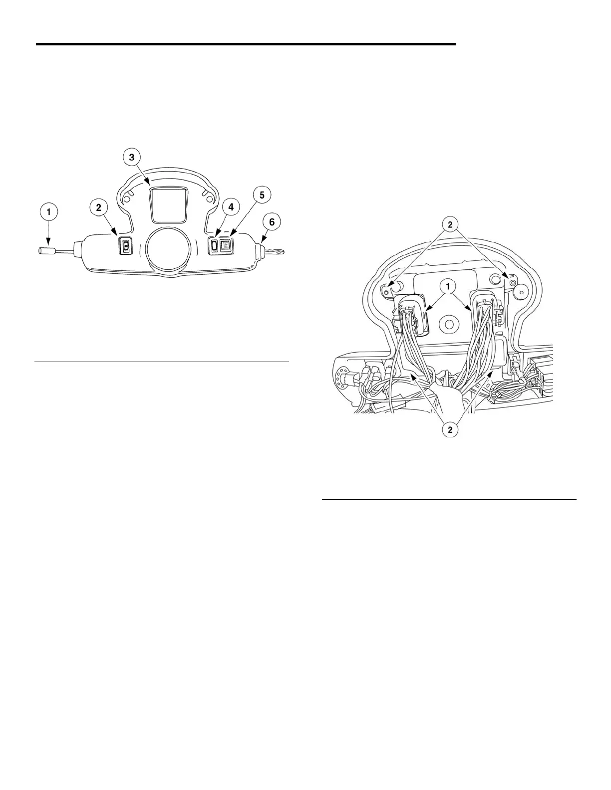
Fig. 23 Instrument Pod
1 - Turn Signal Lever/Windshield Wiper Switch/Horn Button
2 - Light Switch
3 - LCD Display
4 - Trip Reset Button
5 - Drive Mode Switch
6 - Key Switch
The liquid crystal display (LCD) is located in the
center of the instrument pod and performs the
following function.
1. State of charge and charging indicator
2. MPH/KPH speed indicator
3. Accumulated miles/kilometers
4. Drive mode indicator
5. Fault code display
6. Warning indicators and turn signal indicators
OPERATION
At key on, the state of charge indicator displays
remaining battery capacity. The remaining battery
capacity is displayed in a bar type graph. For
example, 8 green bars indicate 80% charge, 1
yellow bar indicates 10% charge, and 1 red bar
indicates less than 10% charge.
REMOVAL
1. Remove upper dash panel. See Upper Dash in
Body, section 7.
2. Remove lower dash panel. See Lower Dash in
Body, section 7.
3. Remove RH and LH pod covers. See Pod
Covers in the Body section.
4. Disconnect the 2 electrical connectors.
5. Remove the 2 screws at back of LCD mounting
bracket
Fig. 24 Instrument Pod (Rear View)
1 - Electrical connectors
2 - Mounting screws
INSTALLATION
1. Install the 2 screws into LCD.
2. Attach 2 connectors to back of LCD.
3. Install RH and LH pod covers. See Pod Covers
in the Body section.
4. Install lower dash panel. See Lower Dash in
Body section.
5. Install the upper dash panel.
 Loading...