ELECTRICAL 5 - 2
November 2007 GEM Service Manual
ELECTRICAL SYSTEM
DESCRIPTION
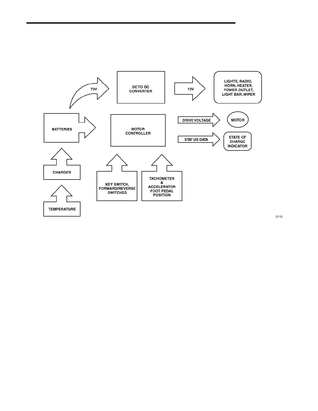
Fig. 1 Electrical System Diagram
The electrical system of the GEM is shown in the
block diagram above. For purposes of operational
description, the system is divided into three groups
the Power System, the Drive System and, the
Accessory System.
WARNING: Always turn off the Master
Disconnect Switch and allow a few minutes for
the system to discharge before servicing the
electrical system. Never wear loose jewelry,
rings or watches. Always use insulated tools to
prevent shorting.
NOTE: The master disconnect switch is located
in the lower dash unit of the fuse access panel
(see figure 4).
 Loading...