5 - 35 ELECTRICAL
GEM Service Manual November 2007
MOTOR
DESCRIPTION
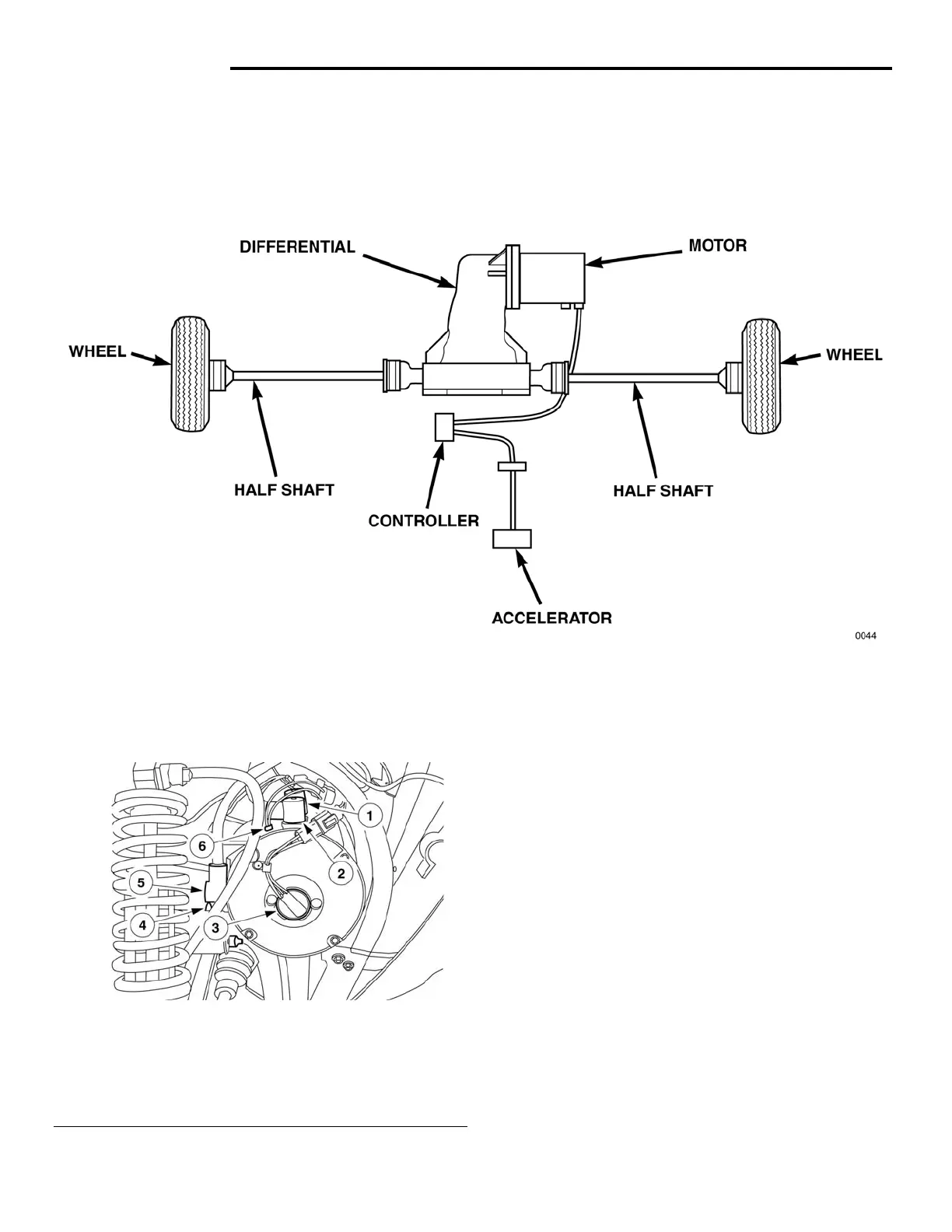
Fig 19 Motor Location
Power to the drivetrain is supplied by a 72-volt electric motor, which is attached to the differential. The motor
speed (RPM) is monitored by a small magnet and a speed sensor (tachometer) mounted to the center rear of
the motor (see figure 20).
Fig 20 Motor Electrical Connections
1 - Motor Field 1 (F1) 6 - Motor Temperature Switch
2 - Motor Armature 2 (A2)
3 - Speed Sensor (Tachometer)
4 - Motor Armature 1 (A1)
5 - Motor Field 2 (F2)
OPERATION
Motor activation and speed are controlled by the
motor controller based on the signal from the
potentiometer located in the accelerator pedal in the
cab. A splined cup in the motor is connected to a
splined shaft on the pinion gear in the differential.
Rotational motion of the motor's cup transmits that
motion to the differential.
DIAGNOSIS AND TESTING
Refer to the Drive and Power System
Troubleshooting Chart B. The circuit diagrams
provided in this manual are also useful in isolation of
problems.
 Loading...