5 - 17 ELECTRICAL
GEM Service Manual November 2007
ACCELERATOR PEDAL
(FOOT PEDAL)
DESCRIPTION
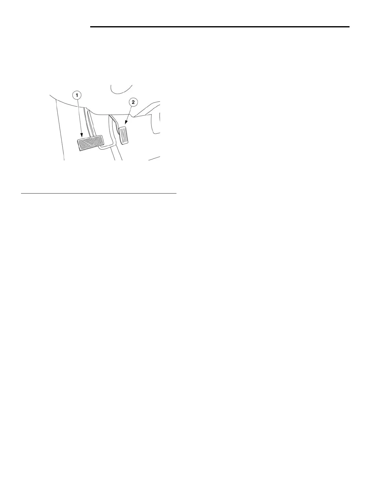
Fig. 8 Foot Controls
1 - Foot Brake Pedal
2 - Accelerator Pedal
The accelerator pedal (see figure 8) is located on
the floor, close to the center of the vehicle and is
used to control vehicle speed.
OPERATION
Pressing down on the pedal will increase speed.
Letting up on the pedal will reduce power to the
electric motor and vehicle speed will slowly
decrease.
DIAGNOSIS AND TESTING
The accelerator pedal module consists of two
electrical components - the accelerator
potentiometer and the start switch. Testing for
accelerator potentiometer and the start switch are
described separately below. It may be helpful to
reference the Motor Circuit electrical diagram while
testing these components.
ACCELERATOR POTENTIOMETER TESTING
1. Disconnect 23-pin connector CH1 located on
the top of the motor controller (under the hood
assembly).
2. Using an ohmmeter, measure the resistance
between pins 9 and pin 7. When the accelerator
pedal is in the UP position, the ohmmeter
should read approximately 3000 ohms. Push
the accelerator pedal down; the resistance
between pins 9 and 7 should gradually
decrease. When the accelerator pedal is
completely down, the resistance should reach
approximately 80 ohms. If the resistance does
not vary as described, replace the accelerator
pedal. If the resistance is a constant very low
resistance (possible short circuit) or constant
high resistance (open circuit), there could be a
problem with the wiring harness between the
motor controller and the accelerator pedal
module or there could be a faulty accelerator
pedal.
3. Using an ohmmeter, measure the resistance
between pins 9 and 8. The resistance between
these two pins should remain approximately
3000 ohms regardless of the position of the
accelerator pedal. If the resistance is very high,
there is probably a broken wire between the
motor controller connector and accelerator
pedal, or there could be a faulty accelerator
pedal.
START SWITCH TESTING
1. Disconnect 23-pin connector CH1 located on
the top of the motor controller (under the hood).
2. Using an ohmmeter, measure the resistance
between pin 3 and the – 72 volt ground on the
motor controller. With the accelerator pedal UP,
the circuit should be open (high resistance).
With the accelerator pedal pressed, the
resistance should be 0 ohms (start switch is
closed). If the resistance does not vary as
described, replace the accelerator pedal.
REMOVAL
1. Remove upper and lower dash panels. See
Body, section 7.
2. Disconnect the foot pedal wire harness
connector.
3. Remove the bolts and the pedal.
INSTALLATION
1. Place the pedal housing back in its floor
position and install the bolts.
2. Connect the foot pedal wiring harness
connector.
3. Install the upper and lower dash. See Body,
Section 7.
 Loading...