Administrator’s Guide for Polycom HDX Systems
2 - 16
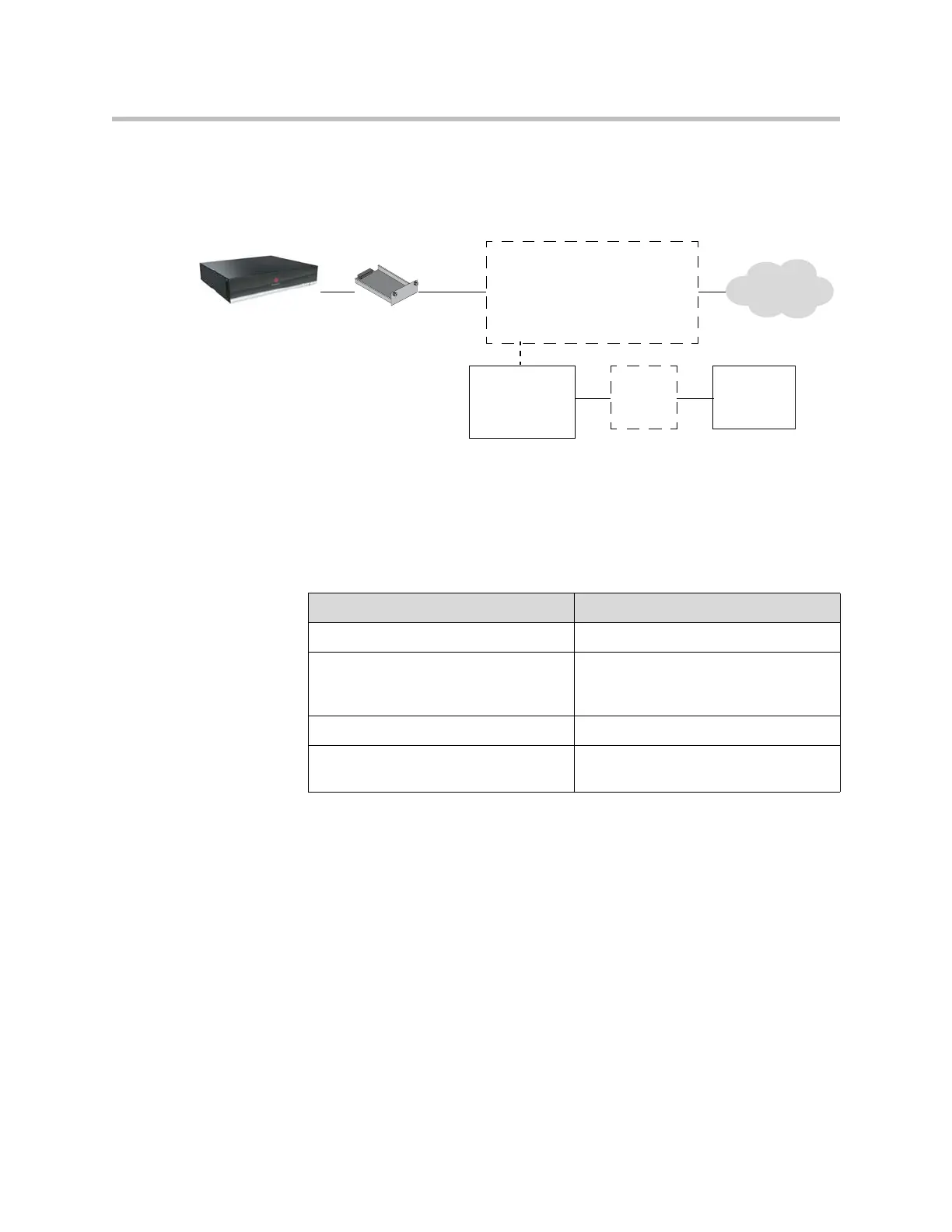
The diagram below shows a general view of how network interface modules
are connected in Polycom HDX systems.
PRI Network Interface Status Lights
The network interface lights are located on the network interface module.
Additional device
Examples:
PRI — CSU
V.35/RS-449/RS-530 —
encryption equipment
Network
interface
module
External
power
supply If
using PRI
UPS
Power
source
Network
Polycom HDX
system
+
When the PRI network interface... It means...
Indicators are off No power to the system.
Red indicator is on or blinking The system is not connected to the
ISDN network, or there is a problem
with the ISDN line.
Yellow indicator is on or blinking There is a problem with the ISDN line.
Green indicator is on The system is able to make and receive
calls.

 Loading...