Chapter 6: LEDDescriptions
LEDs for 12-, 24-, 48-Drive Systems
QX and QXS Setup Guide 169
Controller I/O Module for 12-, 24-, 48-Drive RAID Chassis
LEDs (Rear View)
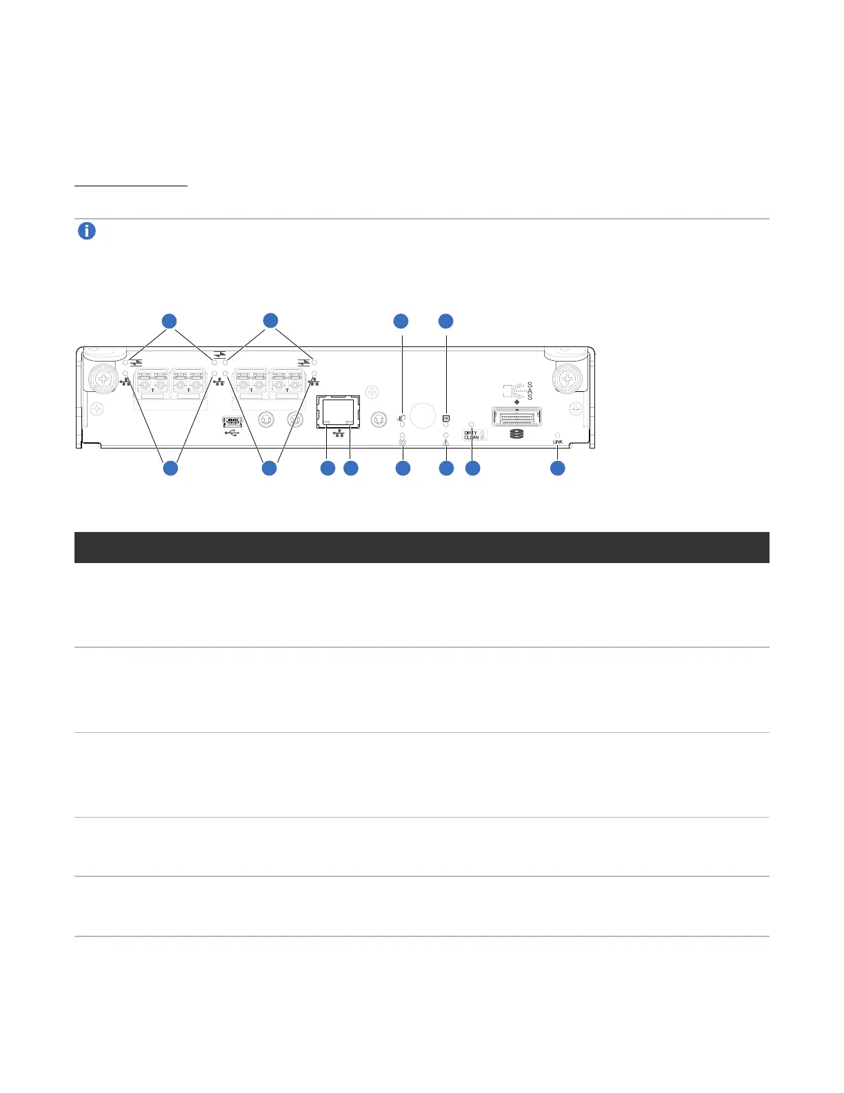
Figure 120 below provides a representative example of the controller I/O module. It lists the location and
description of the controller I/O module LEDs.
Note:QXS-3, QXS-4, and QXS-6 Series systems offer a SAS and a CNC controller I/O module (FC
and iSCSI). The QXS-1200, QXS-2400, and QXS-5600 use only a FC controller I/O module.
Figure120:LEDs: controller I/O module (FC and 10GbE SFPs)
CACHE
CLI
CLI
LINK
ACT
6Gb/s
SERVICE−1SERVICE−2
PORT 0 PORT 1 PORT 2 PORT 3
1
2
3 4
5
6
7
8
9 10
1
2
LED Description Definition
1 Host 4/8/16
Gb FC
1
Link Status/
Link Activity
Off — No link detected.
Green — The port is connected and the link is up.
Blinking green — The link has I/O or replication activity.
2 Host 10GbE
iSCSI
2,3
Link Status/
Link Activity
Off — No link detected.
Green — The port is connected and the link is up.
Blinking green — The link has I/O or replication activity.
3 Network Port
Link
Active
Status
4
Off — The Ethernet link is not established, or the link is down.
Green — The Ethernet link is up (applies to all negotiated link speeds).
4 Network Port
Link Speed
4
Off — Link is up at 10/100base-T negotiated speeds.
Amber — Link is up and negotiated at 1000base-T.
5 OK to
Remove
Off — The controller I/O module is not prepared for removal.
Blue — The controller I/O module is prepared for removal.
Table49:Controller I/O module LEDs
 Loading...