Chapter 6: LEDDescriptions
12-, 24-, 48-Drive Expansion Chassis Rear Panel LEDs
QX and QXS Setup Guide 174
12-, 24-, 48-Drive Expansion Chassis Rear
Panel LEDs
Note:The QXS-2400 SSD ships as a RAID chassis (RBOD) only. The QXS-2400 SSD does not
support any additional drive expansions (JBODs).
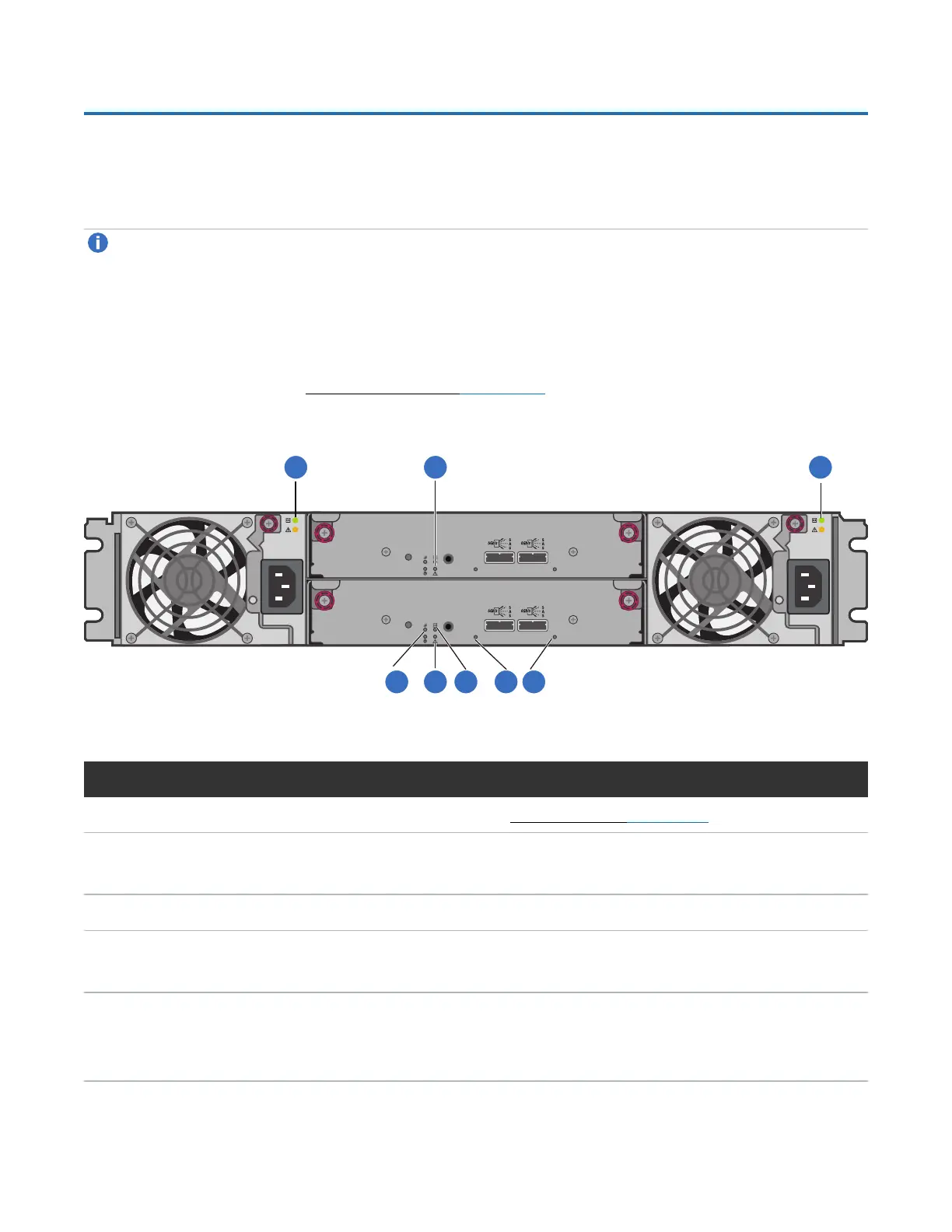
The rear panel layouts of the 12-, 24-, 48-Drive Expansion Chassis are basically identical. All models
support 6-Gbit/s. Accordingly, the expansion chassis feature a “6 Gb/s” label above each SAS
(ingress/egress) expansion port.
Newer models of these drive expansion chassis feature AC power supplies without power switches, as per
the system shown below. See Power On/Power Off on page 85 for more information.
Figure124:12-, 24-, 48-Drive Expansion Chassis
LEDNo./Description Color State Definition
1 — Power Supply — —
SeePower Supply LEDs on page185.
2 — Unit Locator White Off
Blink
Normal operation.
Physically identifies the expansion module.
3 — OK to Remove Blue Off Not implemented.
4 — Fault/Service Required Amber On
Blink
A fault is detected or a service action is required.
Hardware-controlled power-up.
5 — FRU OK Green On
Off
Blink
Expansion I/O module is operating normally.
Expansion I/O module is not OK.
System is booting.
Table52:Expansion chassis rear panel LEDs
 Loading...