Chapter 1: Components
4U56 Drive System
QX and QXS Setup Guide 23
4U56 RAID Chassis: Rear Panel Layout
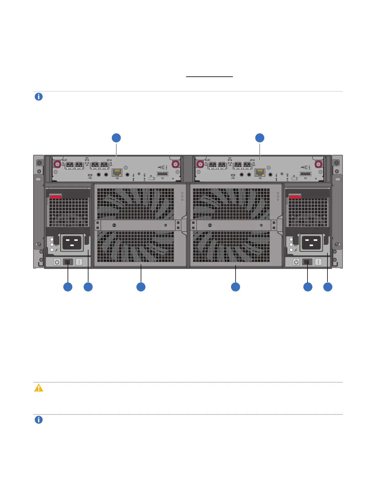
The diagram and table below display and identify important component items that comprise the rear panel
layout of a 4U56 RAID chassis. The following image (Figure 31 below) shows a representative example of
RAID chassis models included in the product series.
Note:The 4U56 Series RAID chassis (4U) is considerably different from the 2U12, 2U24, and 2U48
RAID chassis (2U) systems.
Figure31:4U56 RAID Chassis: Rear Panel Layout
LINK SERVICE–1
CACHE
DIRTY
CLEAN
LINK
ACTSERVICE–2 CLI
CLI
PORT 0 PORT 1
PORT 2 PORT 3
LINK SERVICE–1
CACHE
DIRTY
CLEAN
LINK
ACTSERVICE–2 CLI
CLI
PORT 0 PORT 1
PORT 2 PORT 3
1. ControllerI/OModuleA
2. ControllerI/OModuleB
3. ACPowerSwitch(qty.2)
4. ACPowerSupply(PSU,qty.2)
5. FanControlModule(FCM,qty.2)
The RAID chassis accommodates two Controller I/O modules within the chassis (see callouts No.1 and
No.2 above). A RAID chassis accommodates two power supply units of the same type — either both AC or
both DC — within the two power supply slots (see two instances of callout No.4 above). Beneath each
power supply is a power supply switch (see two instances of callout No.3 above). The RAID chassis
accommodates two fan control modules (see two instances of callout No.5 above).
Caution:The QXS storage configurations are dual-controller. Single-controller support is provided
only when a controller fails over to its partner controller. A controller I/O module must be installed in
each slot to ensure sufficient airflow through the chassis during operation.
Note:The chassis support hot-plug replacement of redundant controller I/O modules, fans, power
supplies, and expansion modules. Hot-add replacement of expansion chassis is also supported.
 Loading...