LTE Standard Module Series
EC200T Series Hardware Design
EC200T_Series_Hardware_Design 40 / 90
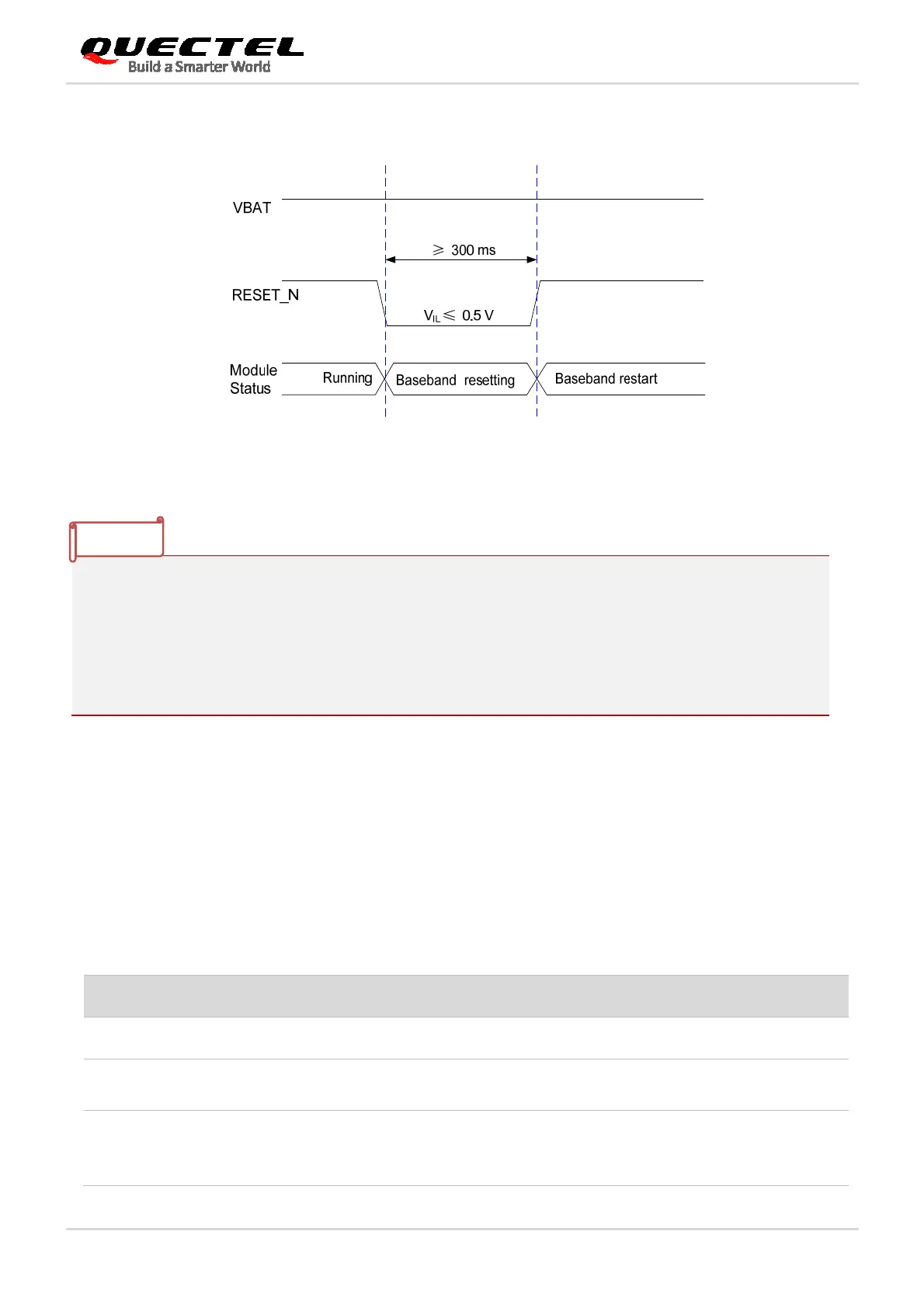
The timing of resetting module is illustrated in the following figure.
Figure 15: Timing of Resetting Module
1. Please ensure that there is no large capacitance with the max value exceeding 10 nF on
PWRKEY and RESET_N pins.
2. RESET_N only resets the internal baseband chip of the module and does not reset the power
management chip.
3. It is recommended to use RESET_N only when failing to turn off the module by AT+QPOWD
command or PWRKEY pin.
3.8. (U)SIM Interface
The (U)SIM interface circuitry meets ETSI and IMT-2000 requirements. Both 1.8 V and 3.0 V (U)SIM
cards are supported.
Table 11: Pin Definition of (U)SIM Interface
Pin Name Pin No. I/O Description Comment
USIM_GND 10 Specified ground for (U)SIM
USIM_DET 13 DI (U)SIM card detect
1.8 V power domain.
If unused, keep it open.
USIM_VDD 14 PO (U)SIM card power supply
Either 1.8 V or 3.0 V (U)SIM card
is supported and can be identified
automatically by the module.
NOTES
 Loading...


