LTE Standard Module Series
EC21_Series_Hardware_Design
15
/ 118
Figure 42: Referenced Heatsink Design (Heatsink at the Top of the Module)............................................. 105
Figure 43: Referenced Heatsink Design (Heatsink at the Backside of Customers’ PCB)..........................105
Figure 44: Module Top and Side Dimensions.....................................................................................................107
Figure 45: Module Bottom Dimensions (Bottom View).....................................................................................108
Figure 46: Recommended Footprint (Top View)................................................................................................ 109
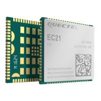
Figure 47: Top and Bottom Views of the Module............................................................................................... 110
Figure 48: Reflow Soldering Thermal Profile...................................................................................................... 112
Figure 49: Carrier Tape Dimension Drawing.......................................................................................................114
Figure 50: Plastic Reel Dimension Drawing........................................................................................................114
Figure 51: Packaging Process.............................................................................................................................. 115
 Loading...


