Measurement basics
R&S
®
LCX Series
47User Manual 1179.2260.02 ─ 02
5 Measurement basics
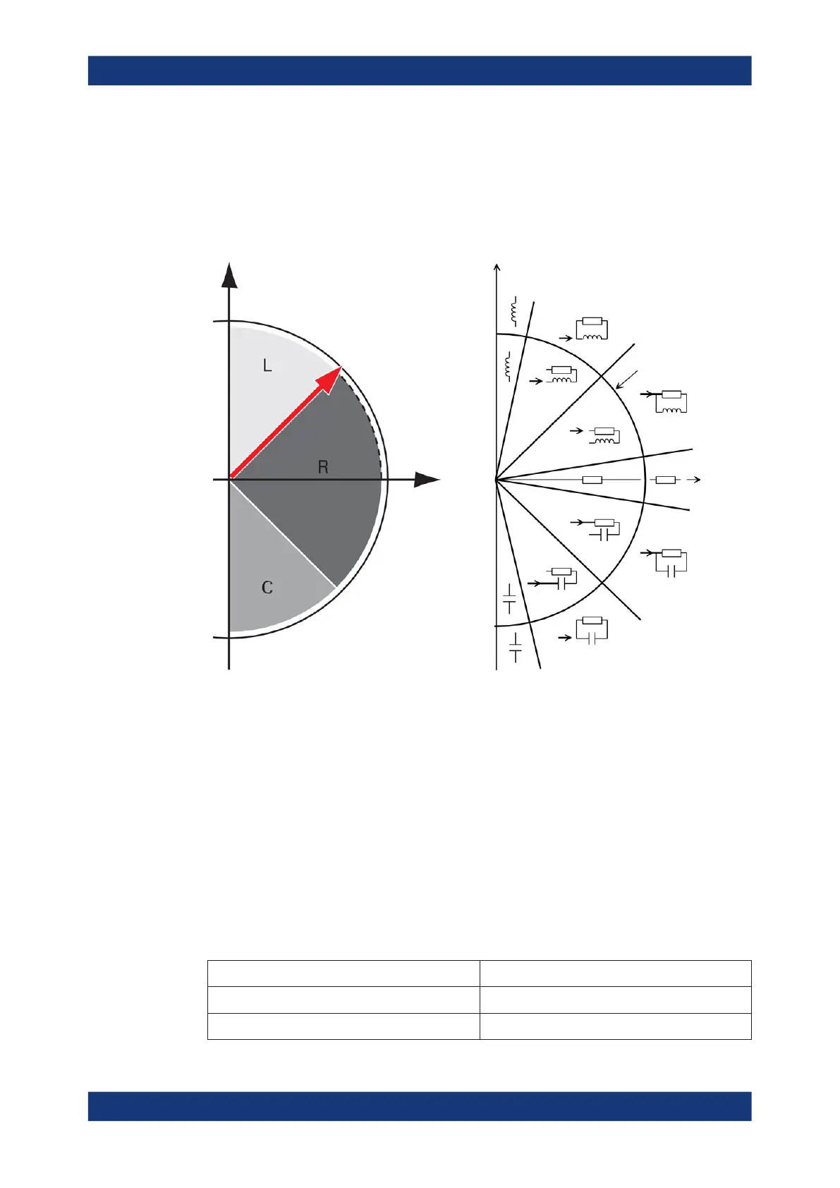
The following graph shows the capacitive and inductive parts of passive components
during impedance measurement in dependency on the frequency and the phase shift.
phase angle
above 45 ° = L
below -45 ° = C
Real axis
Imaginary axis jX
R
Q = D = 1
Q = D = 1
Q = 500
D = 0.002 Ω
|Z| = 1000 Ω
Q = 500
D = 0.002 Ω
Q = 500
D = 0.002 Ω
Q = 500
D = 0.002 Ω
Figure 5-1: Phase angle and integral sections
L = inductance
R = resistance
C = capacitance
|Z| = impedance
D = dissipation factor
Q = quality factor
5.1 Impedance measurement parameters in general
The following table outlines the basic parameters and their definitions:
Table 5-1: Basic parameters and definitions
Parameter (designation and [unit]) Definition
Z (Ω) Impedance
|Z| (Ω) Magnitude of Z
Impedance measurement parameters in general