Chapter 8: Installation 8-1
Introduction
Chapter 8: Installation
8.1 Introduction
This chapter provides installation instructions for the SL72 PLUS Pathfinder
Radar and SL72RC PLUS Pathfinder Radar/Chartplotter system. Details for
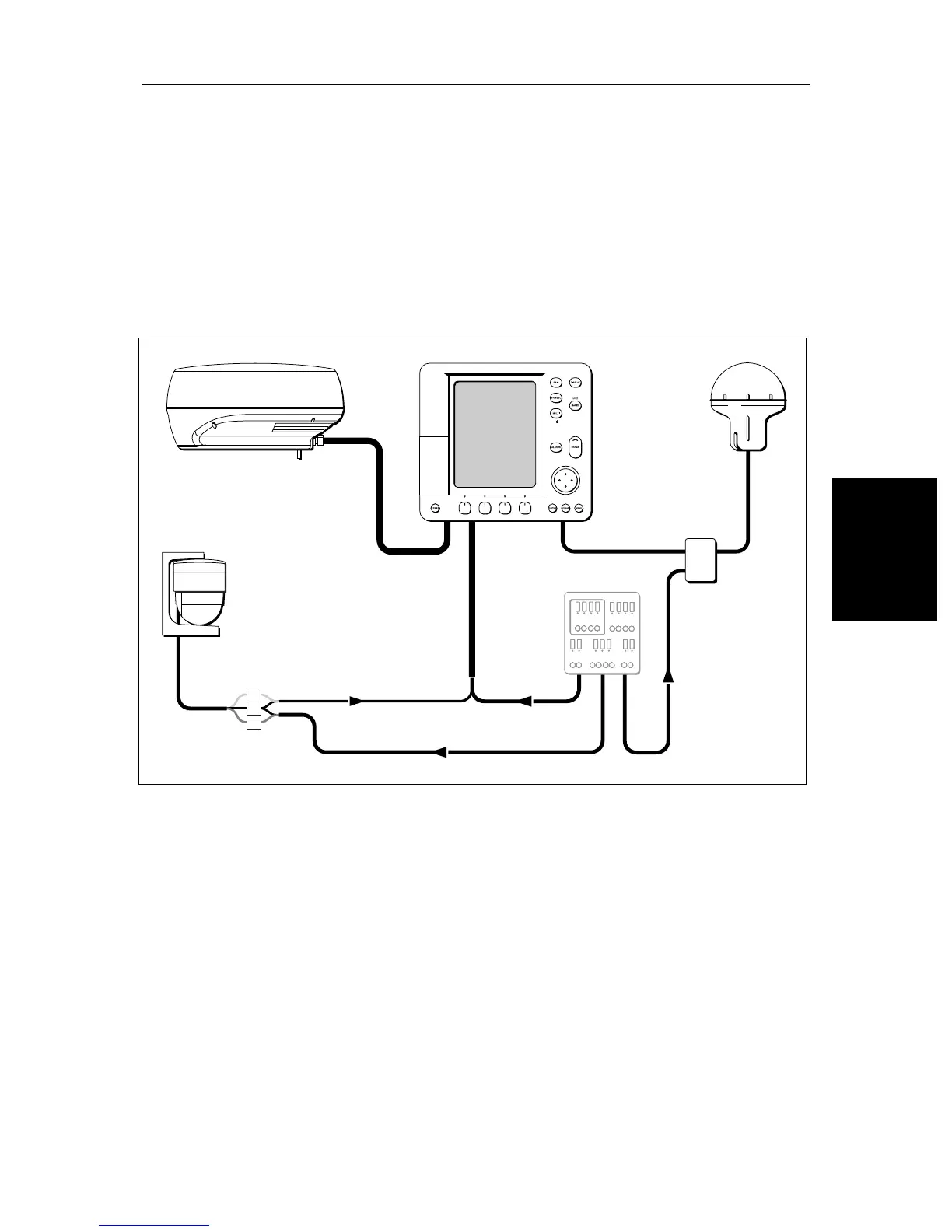
mounting and connecting the equipment are included. A typical radar system
is shown below
Figure 8-1: Typical System
Note: If you wish to practice using the display before installation, connect a
12V or 24V DC power supply (connecting the red wire via a 6.3A quick blow
fuse to positive and the black wire to negative) and using the simulator mode,
as described in Chapter 2.
If you are connecting your radar system to other equipment install then test the
display and scanner as described in this chapter. Once the system is operating
correctly, you can connect the display to other equipment as described in
Section 8.11, taking particular care to ensure the correct polarity of the
SeaTalk supply. Section 8.11 describes the SeaTalk and NMEA interfaces.
For full functionality of the radaryou need to provide position and heading
data.
NMEA
SeaTalk
Display Unit
Distribution Panel
D4288-4
Scanner
12/24V Supply
12V Supply
12V Supply
Junction
Box
GPS
Compass
 Loading...