Chapter 8: Installation 8-15
Connecting the
Inter-unit Cable to
the Scanner
8.7 Connecting the Inter-unit Cable to the Scanner
CAUTION:
Before wiring the scanner unit, make sure that the inter-unit cable is not
connected and power is not applied to the display unit.
When you have run the inter-unit cable to the scanner location, connect the
cable as follows:
1. Loosen the 4 screws securing the scanner cover. These screws are captive
and should remain assembled to the lower flange assembly. Press the
radome inwards to release the top. This breaks the seal and makes removal
easier.
2. To avoid losing the scanner cover, tie the cord, attached to the inside of the
base of the scanner, to the eye provided in the cover.
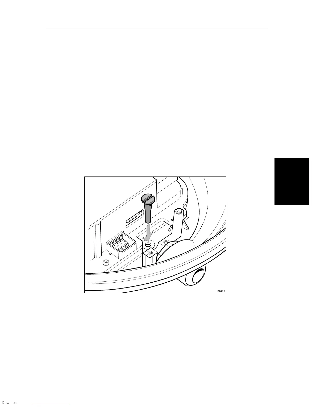
3. Remove the drain tube from inside the base of the scanner, and insert it into
the drain hole as shown in the following diagram. Pull the tube gently from
outside the scanner so that it clips into place.
Figure 8-8: Fitting the Scanner Drain Tube
4. Referring to Figure 8-9, remove the securing nut (1) from the watertight
gland and grommet (2), where the inter-unit cable (3) will enter the base.
5. Slide the gland nut (1) onto the inter-unit cable (3), and insert the cable, still
covered by its protective sleeve, through the gland and grommet into the
base.
6. Carefully cut and remove the protective sleeve to expose the 8-way plug
(4) and power cores (6). Place the cable in the earthing clamp (9), ensuring
that the exposed wire braid sits in the earthing clamp.
D3937-3
 Loading...