8-20 SL72 & SL72RC PLUS Pathfinder Radar & Radar/Chartplotter
System
Connections
8.9 System Connections
Grounding the System
It is important that an effective RF ground is connected to the system. You
must ground the display by connecting the drain wire (shield) of the Power/
NMEA Input cable to the nearest ground point of the ship’s RF ground system.
If you need to extend the wire, the extension wire should be an 8 mm braid or
AWG 10 (6.0 mm
2
) multi-stranded cable.
If your vessel does not have an RF system, connect the drain wire to the
negative battery terminal.
DC Power Connection
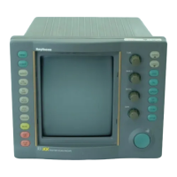
The SL72 PLUS Pathfinder Radar and SL72RC PLUS Pathfinder Radar/
Chartplotter systems are intended for use on ships’ DC power systems rated at
12 V or 24 V . Power is supplied to the scanner via the display unit.
The DC system should be either:
• Negative grounded, with the negative battery terminal connected to the
ships ground.
• Floating, with neither battery terminal connected to the ships ground.
CAUTION:
This system is not intended for use on “positive” ground vessels.
The power cable Ground (earth) connections must be connected to the
ship’s ground as described above.
The power connection to the display should be made at either the output
of the battery isolator switch, or at a DC power distribution panel.
Raymarine recommends that power is fed directly to the display via its
own dedicated cable system and MUST be protected by a thermal circuit
breaker or fuse, installed close to the power connection.
Table 8-5: Isolator Switch/Thermal Breaker/Fuse Values
Vessels Supply Device Value
12 V
Isolator Switch min. rating 20A
Thermal Breaker rating 10A
Fuse value 15 A
24 V
Isolator Switch min. rating 15 A
Thermal Breaker rating 5 A
Fuse value 8 A
 Loading...