Installation
MP150 Rev. E3 07/2013 19
Refer to section 2.2 Optical Specifications, page 9, for basic versions of optical resolution values for the
various models.
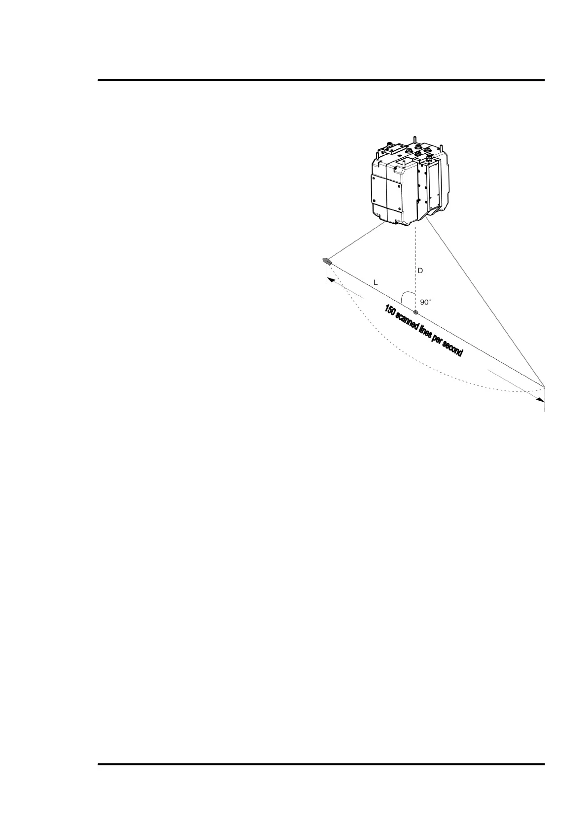
Figure 7: Relationship between scan line width and distance to target
The relationship between the scan line width (L) and the distance (D) to the front side of the
linescanner housing is defined as described above. For long distances, the scan line width is about
twice the measurement distance (90° FOV).
5.5 Mounting
The linescanner can be installed as follows:
• on a tripod with a standard 1/4-20 UNC (photo equipment) thread. This type of setup requires
the optional tripod mounting plate (XXXTMP50ACCC) and is recommended if the linescanner
is to be used only for temporary or mobile measurements.
• with the mounting holes of the linescanner housing. This type of setup is recommended for
permanent installations where higher stability is desired.
Prevent all contact between heat sources and the linescanner to protect the linescanner from
overheating.
= Distance to target (measured from front
surface of housing)
 Loading...